• The move to the new server is done. There are some software and database maintenance updates in process. This has us passing the hat around to help out. We appreciate any donations. Seriously, even a dollar helps. The payment page may be found here - https://www.audiokarma.org/support.html

SX-434 FM issues

goldswimmerb

Failed out of engineering, but look at me now!
Subscriber
Hey guys, so following a recap my SX-434s FM board seems out if wack.

The tuning needle, when I'm FM mode appears to be working as if it were in the AM setting. The needle won't deflect past the center point. Then, if FM muting is turned on/off there is a pop. When muting is turned off I get audio, but when it's turned on I don't.

Not quite sure where to look in this one.

Mine appears to be an FV GN KCU unit.

Thanks.
 
Register to hide this ad
Are the function switches clean and intact? The tuning meter signal is switched through these.

Is C21 polarity correct? This can affect the meter operaton.

Is C50 polarity correct? This can affect the muting function.
 
Are the function switches clean and intact? The tuning meter signal is switched through these.

Is C21 polarity correct? This can affect the meter operaton.

Is C50 polarity correct? This can affect the muting function.

I replaced both of those with same value WIMA films, would that cause issues?
 
Are the function switches clean and intact? The tuning meter signal is switched through these.

Is C21 polarity correct? This can affect the meter operaton.

Is C50 polarity correct? This can affect the muting function.
Min also appears to be the later AWE-052 board
 
Testing HA 1137 Gives:
1 - 2.1v
2 - 2.1v
3 - 2.1v
4 - 0v
5 - 1.4v
6 - 5v muting on, 10v muting off
7 - 4.7v
8- 5.6v
9- 5.6v
10 - 5.6v
11- 13.2v
12 - varies between 1 and 5 depending on tuning
13 - 0.1v
14 - 0v
15 - 5.1v
16 - 0v
 
HA1156 Gives
1 - 13.2
2 - 3.11v muting on, when switching off it's drops do .41 then rises. When switching on it jumps to 6.8 then falls.
3 -5.4v on, when switching off it drops to .41v then rises, when switching on it spikes at 11.8v
4 - 11.4v
5 - 11.4v
6 - 13.2v
7 - 0v
8 - 0.2v
9 - 2.4v
10 - 1.7v
11 - 2.3v
12 - 2.42v
13 - 2.42v
14 - 3.28v
 
I replaced both of those with same value WIMA films, would that cause issues?
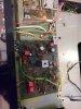
Attached is my board.

C48 has been temporarily relocated to the bottom so I have a little more room to work with.

I also swapped out Q6 and Q7 and that didn't help nor did it make things worse.
 

Attachments

  • IMG_20190909_071901.jpg
    IMG_20190909_071901.jpg
    57.3 KB · Views: 13
Hoping someone can weigh-in as I dont usually deal with tuners. Is it common for either of the two IC's in the FM circuit to go bad?
 
It is uncommon for the ICs to fail, but it does happen. Given that the unit worked before the recap, I would be a little surprised if the IC had failed. The slight change in value/tolerance of the caps could have altered the resonant circuits to the point that alignment is necessary.

Can you list which caps were changed?
 
It is uncommon for the ICs to fail, but it does happen. Given that the unit worked before the recap, I would be a little surprised if the IC had failed. The slight change in value/tolerance of the caps could have altered the resonant circuits to the point that alignment is necessary.

Can you list which caps were changed?
C18, C21,C25, C26, C28,C32, C36, C39, C48, C49, C50, C59, C60, C61
That should be every lytic on that board.
 
I probed the 19khz pin and that was spot on.

Which part of the circuit goes to the meter?
 
If I short pin 8 to ground I get the meter moving in the opposite direction
 
You could try adjusting T5 lower core to center the FM tuning needle per the SX-434 service manual. Without an FM generator, do this on a fairly weak but clear station that has no strong stations close in frequency. Then tune by ear with muting off so it breaks to noise equally on both sides - this where to center the tuning dial. I would try to mark where T5 is now first, if possible. And please use proper plastic tools - not metal ones that will break or crack the fragile adjustment core. In a pinch make a wooden tool from hardwood or a fat toothpick.

It would also help to clean the RF tuning gangs ground contacts first. See the FM forum sticky on how to.

Beyond that, double check all replaced component values are correct, and re-solder all your new component connections, especially ones in the HA1137 area like C25 and C26. The mute circuit is fairly simple on that one, but something is off if it pops on switchover - usually means there is DC on a switch contact that should not be there.
 
You could try adjusting T5 lower core to center the FM tuning needle per the SX-434 service manual. Without an FM generator, do this on a fairly weak but clear station that has no strong stations close in frequency. Then tune by ear with muting off so it breaks to noise equally on both sides - this where to center the tuning dial. I would try to mark where T5 is now first, if possible. And please use proper plastic tools - not metal ones that will break or crack the fragile adjustment core. In a pinch make a wooden tool from hardwood or a fat toothpick.

It would also help to clean the RF tuning gangs ground contacts first. See the FM forum sticky on how to.

Beyond that, double check all replaced component values are correct, and re-solder all your new component connections, especially ones in the HA1137 area like C25 and C26. The mute circuit is fairly simple on that one, but something is off if it pops on switchover - usually means there is DC on a switch contact that should not be there.

The main problem isnt the meter circuit itself as I can still tune the unit, Its that the needle only moves to the right (the AM tune range on the needle) rather than moving to the left as its supposed to.

The popping occurs whenever the unit comes in and out of muting.
 
When the meter is set on FM, and you are tuned properly, the FM meter should be centered. When moving L off channel, it should go one way, and then move the other way when going R.
This is all driven by the discriminator, which is also "zero'ed" when properly tuned. You adjust T5 lower core to re-zero it if you changed something in the circuit, i.e. caps. You are also supposed to adjust the top core of T5 for lowest distortion.
I'm trying to give you the poor man's way to do this with no alignment instruments. If you are uncomfortable messing with it, don't. Get someone else to do it. That thing could use a proper alignment too, if it has never had one.
The meter could be far off to one side because the discriminator is likely way off from zero volts. This is all a remote guess. You could have also bridged two solder points underneath that are not supposed to touch. The possibilities are endless...
 
Back
Top Bottom