• The move to the new server is done. There are some software and database maintenance updates in process. This has us passing the hat around to help out. We appreciate any donations. Seriously, even a dollar helps. The payment page may be found here - https://www.audiokarma.org/support.html

SX 5590-SX 1250 help please.

knownman

New Member
Hello Everyone,
https://audiokarma.org/forums/index.php?threads/sx1250-sx5590-restoration.907820/#post-13669309
I've started the recap and update for my beloved SX 5590. Find that thread above.
And I've encountered my first problem so I'm hoping somebody here can assist with the troubleshooting as it's not my most perfected technique.

I started with the AWM 091 and AWH 048 power amp left channel. I believe I've done a good job of removing, refitting all components in correct orientation, cleaning and touching up some loose solder joints along the way. I'm using the dim bulb tester and everything appears to be functioning, both relays still coming up so I attempted to try and reset the dc offset to 0, and that went fine, but when I adjust VR2 to 100mV per the SM I can only reach 46mV. I did set this before repairing and believed it to be at 100mV but now I've gone and fooled with it and here we are. Items replaced include all of the capacitors, diodes, transistors (tested and matched with curve tracer) as per the latest list by Supernoob or Mattsd. I started troubleshooting myself to verify voltages and such. Here's what I've found.

Protect AWM 091
  • 1 65.6V
  • 2 7.5 VAC
  • 3 -24.3V
Power Supply AWR 107
  • 9 85V
  • 10 -86.7
  • 8 23.4V
Power Amp AWH 048
  • 3 63.83V
  • 2 -63.72V
I've also started pulling measurements at the component level on some of the transistors and have found some discrepancies an example is on AWH 048 Q1 I read -61V across the base where the SM calls for 0V and then 0V across the emitter where -62.5V should be. As I've found some readings to be accurate within a percentage and others reversed entirely I'm wondering if I have failed to set the unit properly prior to taking the measurements. For example if the circuit is designed to be tested with an input signal of a specific voltage say 1V @ 1khz? I've also found Q7 and Q8 to have about half the voltage across their respective bases. I noticed a similar discrepancy on one of the transistors on the protect board. Add to this I've found one inaccurate resistor value written in one section of the service manual but then correctly annotated in another section so I'm wondering if perhaps there are other issues with the copy I'm using. I should add that I've taken readings on all the resistors, diodes and double checked installation orientations of all polarized components. I'm hoping anyone could offer some guidance on what I may be doing wrong, and what I should be looking at. Also as its very difficult to get test leads on each specific point I'd like to measure with the boards fully installed. I have reversed the placement of the protect board which adds some room but I'd prefer to hang the Amp board out the bottom instead. This requires either living the output transistors unplugged, which is what I'm not positive will effect the readings as the ones I could read both ways appear to be the same in this configuration or will I need to build jumpers. Any help is most appreciated.

Thanks,
IMG_3778.jpg
Matt
 
Last edited:
Register to hide this ad
I started with the AWM 091 and AWH 048 power amp left channel. I believe I've done a good job of removing, refitting all components in correct orientation, cleaning and touching up some loose solder joints along the way. I'm using the dim bulb tester and everything appears to be functioning, both relays still coming up so I attempted to try and reset the dc offset to 0, and that went fine, but when I adjust VR2 to 100mV per the SM I can only reach 46mV. I did set this before repairing and believed it to be at 100mV but now I've gone and fooled with it and here we are. Items replaced include all of the capacitors, diodes, transistors (tested and matched with curve tracer) as per the latest list by Supernoob or Mattsd. I started troubleshooting myself to verify voltages and such. Here's what I've found.

Protect AWM 091
  • 1 65.6V
  • 2 7.5 VAC
  • 3 -24.3V
Power Supply AWR 107
  • 9 85V
  • 10 -86.7
  • 8 23.4V
Power Amp AWH 048
  • 3 63.83V
  • 2 -63.72V
I've also started pulling measurements at the component level on some of the transistors and have found some discrepancies an example is on AWH 048 Q1 I read -61V across the base where the SM calls for 0V and then 0V across the emitter where -62.5V should be. As I've found some readings to be accurate within a percentage and others reversed entirely I'm wondering if I have failed to set the unit properly prior to taking the measurements. For example if the circuit is designed to be tested with an input signal of a specific voltage say 1V @ 1khz? I've also found Q7 and Q8 to have about half the voltage across their respective bases. I noticed a similar discrepancy on one of the transistors on the protect board. Add to this I've found one inaccurate resistor value written in one section of the service manual but then correctly annotated in another section so I'm wondering if perhaps there are other issues with the copy I'm using. I should add that I've taken readings on all the resistors, diodes and double checked installation orientations of all polarized components. I'm hoping anyone could offer some guidance on what I may be doing wrong, and what I should be looking at. Also as its very difficult to get test leads on each specific point I'd like to measure with the boards fully installed. I have reversed the placement of the protect board which adds some room but I'd prefer to hang the Amp board out the bottom instead. This requires either living the output transistors unplugged, which is what I'm not positive will effect the readings as the ones I could read both ways appear to be the same in this configuration or will I need to build jumpers. Any help is most appreciated.

Thanks,
View attachment 1835075
Matt

You have a lot of things listed you would like addressed, I will try and get through them step by step. Forgive me if I seem like I am being short and critical, that is not my intent, just trying to be clear and concise, and hopefully informative.

You state you are using the dbt while doing these settings and tests. What wattage bulb are you using?
The dbt protects the amp by choking down the power coming in, so many of the voltages and settings are unreliable while on the dbt.

You are trying to set bias while on dbt. You can test the bias adjustment to see if it varies the bias (functionality) but you cannot set it correctly while on the dbt. Once you see that the pot actually changes the bias setting you should set it back to minimum (fully counterclockwise as per the SM). If you leave it turned up and apply full mains voltage to the unit you may well fry a number of expensive components, like the driver transistors and output transistors.

The voltages listed in your table look fine, pins 2 and 3 are the power supplies for the AWH-048, and they are a bit soft because of the dbt. Also the Stabilizer adjustments in the SM cannot be set perfectly while on the dbt either.

The AWH-048 power amps will DC balance without the output transistors plugged in, so you can set dc offset to 0vdc, but you will have to recheck/reset it after you plug in the output transistors. Bias cannot be set without the output transistors plugged in because it is the current through them you are measuring and adjusting. After you do plug in the outputs bring it up on the dbt to be sure the bulb goes dim. Once you have replaced all the parts you are planning on, completely reassemble the boards into the chassis, and pass the dbt the final time. Then you can go to full mains power and do the final setting of the stabilizer, the bias and the dc offset.

I don't understand what you mean when you say 'across the base' or 'across the emitter'. This a semantics question, those are single points on the schematic so there is no 'across'. You can measure 'across' a resistor because it has two ends to measure. Most would say 'at the base of Q1' which would be clearly understood. That kind of a statement usually implies that the other lead is connected to the chassis ground reference.

Setting dc offset, bias and stabilizer voltages should be done with no input signal present. The SM gives the input sensitivities of the various inputs, e.g. the Aux input is spec'd at 150mV into its 50kΩ impedance. That means that a signal (frequently 1k like you said) at that level will allow the amp volume control to be turned up to reach the maximum specified power output, into an 8Ω dummy load.
The power amp input is specified at 1v, that level input will drive the power amp output to 39v into 8Ω, for a power output of 190W. Look over the Level Diagram and stage gains on page 19 of the SM.

Service Manuals do sometimes contain errors, others here with more specific experience can address those better than I.

If you are actually getting "AWH 048 Q1 I read -61V across the base where the SM calls for 0V" you may need to verify you are looking at the correct leg of the transistor, they are not all the same order. Part of the reason I make that suggestion is that you had already set the dc offset, which is controlled by the differential amp made up of Q1 and Q2, and said it set correctly. If there actually was -61v at that base the dc offset would be radically out of spec.

Most of the components in these units are 5% or 10% tolerance, so, unless an adjustment setting is specified, 5-10% tolerance on voltages you measure are probably OK. The final question is 'Does it work properly?'. One of the hardest lessons I had to learn was to let go of my OCD perfectionism and accept that things have a tolerance because that's just the way technology works:rolleyes:. I am not telling you to ignore your measurements, just take into account allowable tolerances and don't over think things. This is a wonderful hobby and a great forum, don't let me scare you away. Keep asking questions! Welcome to Audiokarma :thumbsup:.

Hello Merlynski and thank you for the thorough reply. I don't mind being more specific and learning the proper terminology will go along way so please keep it coming. I should have been more specific when I mentioned the dim bulb testing. I have a 150 watt bulb. But more to the point you have mentioned, I removed the system from the DBT once it appeared all was working and no signs or smells of smoke. I did the dc offset and further tests with it on mains power no DBT. I attempted to set bias with the system rebuilt and everything in its place. This is when I first discovered the inability to gain more than 46mV. In comparison the right amp has much more gain available and is easy to set to 100mV.
Regarding the across comments I should have said at the base and or at the emitter with ground on the other end. I was quite methodically on the removal and replacement of each of the transistors. I took photos and verified each one I returned into the same orientation as per the SM. I will likely go back and recheck each of the transistors again just to make 3 or maybe now 4 times sure but a fresh day brings new outlook.
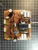
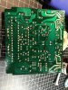
I haven't tested with load yet and paused in the rebuild as I didn't want to open up a bigger can of worms before I get this figured out. I don't know if pictures of completed boards will offer any assistance. Likely not but I'll add a few just the same. Please don't mention the coatings on these. I have some conformal coating which I will apply once all the repairs are mastered.
Thoughts on the next step? Everyday I come back to it with new ideas but I really hope the expertise and wisdom of this forum will prove to be the saviour.

best regards,
Matt
IMG_3755.jpgIMG_3756.jpgIMG_3754.jpgIMG_3753.jpg
 
Last edited:
That 680 Ohm resistor on the protection board HAS to be replaced with a 3W and the resistor next to it normally has heat damage as well. The filter cap bleeders should be 5W and raised off the board. I always see cold solder joints there.
I hope you bumped up resistors in wattage on the power stabilizer board as well.
1250's act fine on even a 75W bulb, I did one last week.

I would swap amp boards for kicks, make sure the issue follows.
Then I would start comparing resistances from the working board to the other.
 
Hello Ivandezande. I had troubles even finding the 150watt bulb. Apparently incandescent filament are going away in most stores around here.
Copy that on R24, R25 5 W and R23 3 W
I actually haven't touched any resistors. It wasn't on my list to do but I'm more than willing to go down that path especially if its recommended for a long life on this gem. I Also haven't done any work aside from these two boards. I believe somebody previously reworked the power stabilizer board and I will rework as well just because it will let me see everything and time stamp the entire unit once completed. Is there a link to the recommended resistors most likely needing replacement/upgrade? I can start searching as well.

Hello Kdris 10. I'm not positive I know which traces you are referring to but I suspect you may have noticed there were two partially lifted pads. Quite the eye you have. These were checked for continuity to their adjacent components and are good. I also verified the continuity at the time of rework. Also noted that during the desoldering of many of the leads especially on the protection circuit, the pads were left with a partial area devoid of copper. I used a new to me Hakko FR301 for the desoldering process and have it in between 1 and 2, the lowest heat settings so I think I've not done anything wrong, just appears this old board is showing it's age a bit. The pictures also don't show it but the amp board does have some warpage as well. And I did verify that when they are installed in their steel trays there are not close to any of the leads. Also ensured the new 470uF caps on the board sit low enough to not touch the bottom of the protection board steel tray. It's really amazing how big this amp is and yet how little room there is to work.

Matt
 
Hello Ivandezande. I had troubles even finding the 150watt bulb. Apparently incandescent filament are going away in most stores around here.
Copy that on R24, R25 5 W and R23 3 W
I actually haven't touched any resistors. It wasn't on my list to do but I'm more than willing to go down that path especially if its recommended for a long life on this gem. I Also haven't done any work aside from these two boards. I believe somebody previously reworked the power stabilizer board and I will rework as well just because it will let me see everything and time stamp the entire unit once completed. Is there a link to the recommended resistors most likely needing replacement/upgrade? I can start searching as well.
Matt
Oh 150 is fine, yeah bulbs are tough. I was just saying that cause someone said you might need a bigger bulb.

Cool. Not that I know of, for whatever reason nobody puts them in BOM lists which absolutely baffles me. My method is any resistor that is discolored and/or has cold solder joints gets replaced and bumped up in wattage.
 
OK, your reply cleaned up a lot of things I did not understand clearly. It appears you do have a bias adjustment problem on one board. ivandezande's response shows exactly why AK is such a wonderful resource, that is all valuable information I did not know. Swapping the boards identifies if wiring and bad output transistors are causing your problems, or if it is the board.
I would love to have an SX-1250 :cool:.
 
Cool. Not that I know of, for whatever reason nobody puts them in BOM lists which absolutely baffles me. My method is any resistor that is discolored and/or has cold solder joints gets replaced and bumped up in wattage.
I have to agree whole heartedly about some resistors needing up-rating for power dissipation. It may be that resistors are easier to find up-rated replacements for and don't adversely affect the function like wrongly specified transistors or capacitors.
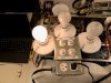
For higher wattage dbt bulbs I just use a Y connector and put two 60W bulbs in it:

DSCF0847.JPG
 
I do this. I can turn any on individually or in parallel or bypass entirely.

100W was fine for my SX-1250, to come out of protection.
 

Attachments

  • dbt.jpg
    dbt.jpg
    106.6 KB · Views: 14
Hello everyone and sorry for the pause in the thread here. This pandemic has certainly altered life around here and I found myself having my attentions reverted to more important tasks but I have today resumed my work. I hope everyone out there is in good health and ok.

I decided to swap the left and right amp boards to see if I would have the same problem with the forward biasing on VR2 only on the opposite side and the result was the issue followed the board. After looking over the board again I just couldn't find any issues that I would have caused so I made the choice to remove the transistors Q9 and Q10 and put back the original pieces. Low and behold I am now able to achieve 100mV of forward bias. Theres not as much more bias available as compared to the OEM right power board but its making the numbers.

One of my chief concerns stemmed from when I was evaluating each transistor with the "suggested replacement". I'm testing each piece on my B&K Precision 501A Semiconductor Curve Tracer. Admittedly I'm not an electronics engineer so take this all for what its worth. I noticed quite a variance in gain on almost every recommended transistor on this board as compared to the original. In most cases the replacement was lower than original.

In the case of the Q9 and Q10 I matched them to be as close as possible within what I had delivered from Mouser or Digikey. I've also ordered at least twice the amount of pieces for each transistor needed in the BOM to allow for filtering out high or low spec pieces. Within each of the 15 or 16 different transistors needed for this refurbishment as per the BOM I have found maybe 2 or 3 of these to have consistently close gains levels amongst the other transistors i received. But again they are not consistent with the OEMs thus far.

My question to this forum is, does everybody believe in swapping known good and working transistors out on their receivers simply for the piece of mind it brings despite knowing that these are not really very well matched replacements? Or are the discrepancies I'm seeing negligible in the grand scheme of things and should I not be looking at this so closely?

I'm not sure but I have some doubts now especially after having this issue and troubleshooting the fix.

Thoughts,

Matt
 
Last edited:
Back
Top Bottom