• The move to the new server is done. There are some software and database maintenance updates in process. This has us passing the hat around to help out. We appreciate any donations. Seriously, even a dollar helps. The payment page may be found here - https://www.audiokarma.org/support.html

SX-626 Problem - Has this happened to you? (I hope to focus repair)

tusntuk2

Active Member
Greetings, AK'ers. Thank you for tuning in here. I was listening to a digital conversion from my TV in AUX, signal had lots of heavy bass rumbling in the scene, and the 626 went "pop" and there was distortion on the left output. This unit has been recapped, it has been working well for two years. Here's the funny thing (to me) - the output signal is clear in the headphone jack, from all input sources, but it is weak and distorted when speakers are attached. Is there a clue here about where to start looking for the problem? (mains?) The schematic shows the same output to the speakers as to the headphone jack (with resistance), so why would it distort in one and not the other? Yes, I tested the speakers and used a second set as well, same results, speakers are fine.
Anybody had this problem before, and might help narrow the focus for a quicker fix? Thank you so much!
 
Register to hide this ad
I think you blew an output transistor or driver transistor. Headphones are less of a load than speakers. It is possible that the speaker relay is bad, but the heavy bass and pop sounds like something failed. Do you have a scope?
 
Output transistor would be my second guess, actually. Not everyone understands that heavy, boosted bass requires huge power. It's easy to drive a moderate powered amp into clipping with the modern addiction to thundering bass, it takes a lot more power than most amps can reliably produce.
 
Did the recapping of the unit include the regreasing of the output transistors to the heat sink? Maybe not.

That thermal transfer medium dries out and shrinks over long periods of time, allowing the gaps to reopen, and the transistors to run hotter, eventually they succumb to the abuse.
 
Thank you, gentlemen! Excellent feedback here.
Protection relay.
The relay seems to work correctly, although I don't fully understand how a relay could create the distortion. Don't they either work (connect) or not?
I do realize the extra load with extra bass. The main filter cap was increased to 4700u, a modest increase. The output caps were boosted to 3500u.

There is a note in my notes about replacing the 945 Q2 in the power supply with a 2383, which I have not done, but it was working well for about two years. in case that might be a factor, I mention it here. I have not taken any voltages yet.

I think you blew an output transistor or driver transistor. Headphones are less of a load than speakers. It is possible that the speaker relay is bad, but the heavy bass and pop sounds like something failed. Do you have a scope?

I was guessing output or driver, but I asked first because they're all soldered in and a project to reach. The amp does operate in this condition, and I can get some voltages. I do have a scope, but I don't know how to use this gift. The 626 has a preamp-main split available.

Did the recapping of the unit include the regreasing of the output transistors to the heat sink? Maybe not.

No, I did not regrease these outputs. Good point. I can do that.
Is there an easy way to check the outputs? I'll fire it up and compare the sides, then report .

Thanks again, everyone!
 
If you tap on the relay and the sound clears up or gets worse, it's the relay.
There are tutorials on Youtube showing how to use a scope. You could input a sine wave and probe the output, before the relay. If it's distorted there, see which side of the sine wave is clipped. That will tell me which part of the amp it could be.
 
If the protection relay has been operated at high output, the spark from opening and closing can corrode or pit the contacts. When that happens you introduce low value resistors and diodes into the signal path, with distortion being the result. Same as a dirty switch.

I'd guess that one of the outputs failed open, or possibly a driver transistor and that will give you a weird waveform on that channel.
 
Good advice, all. Good explanation on the relay, I have not had that particular problem before, but then again I have usually changed the relays when rebuilding. The voltage readings I got from the outputs are probably telling - (full AC, all controls at 0, no load)

Q11 = B .59v, C 19.76v, E 13.9v
Q9 = B 27.3v, C 59.7v, E 26.7v
Q10 = B 19.7v, C 59.7v, E 19.7v
Q12 = B 0.0v, C 26.8v, E 0.0v

I'll pull Q11 first, it looks wrong. Why do Q9 and Q10 have a discrepancy? I'm thinking they should be very similar. Is it affected by the bias setting? I believe Q9 matches what the schematic says (1971 model), but I think Q10 and Q12 are the side of the amp that is working. The schematics skip from PCB to PCB, so it gets a little tricky when identifying wires.
 
Duh, silly me! I have two units open on the bench, a Pioneer SX-727 (with a relay) and now the SX-626 - but the 626 doesn't have a relay, and I glanced at the wrong unit before when answering. So that's not the problem here. I still learned something!
 
Ha! Yeah, got me! I apologize for the stupid mistake, but at least it has no bearing on this problem. With the relay reference I naturally looked at the one with the relay - in the wrong stereo - but I had replaced that one with new, so I didn't think that was the problem. I was eager to solve this, and careless about which unit I observed...anyway...brain fart...

The 626 has four output tx's. Looking straight from the front, top view, I figure Q12 on the far right, closest to the right outside edge, then Q10, Q9, and Q11 on the inside toward the middle of the unit. Please help identify these correctly, as it is difficult for me to match wires, S/M's, and actual, due to the various separate pieces and views. I believe Q10 and Q12 are the Right output, and the Left output is the one with the fuzz in the speakers. This would correspond with the voltage readings on Q11 being suspect. That's as far as I have gotten, but today I will take apart the board to get the mains out for testing. They are soldered in, no sockets, and it will give me an opportunity to regrease them, too. I will also test the drivers while I'm open.

Part of the way I asked the original question was because I wondered if others were using a digital converter from their TV output into their analog stereo like I do. If you are familiar with digital audio signal, you know heavy bass from the sound source can cause clipping. When it overloads it becomes heavy static snap/crackle/pop garbage, a terrible signal for a preamp to deal with, and certainly a bad surge. It was at that instant that the amp went out. I suspected the preamp, hoped it was, actually, but that checks out fine and the outputs don't. It may still be a good question to consider. Perhaps there is a way to avoid this in the future.

I'll post the test results for the outputs when I can.
 
Two solutions: Turn the volume down. Get a powered subwoofer and a crossover to put the heavy bass on the subwoofer and not the Pioneer.
 
First output transistor test on Q11, out of circuit, on a cheap transistor tester, shows hfe=79, 550mw.
All six ways pass using a DMM.
I ran out of time for more.
Looks like we have more digging to do. Suggestions? Drivers? Trimmers?
 
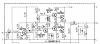
upload_2022-10-30_18-45-15.png

1. Measure the voltage on the 2 collectors of the output transistors. One will be the Vcc, the other should be half the Vcc. Do this on both channels.
2. VR1 adjusts the mid point voltage above. If it's off, see if you can adjust it, if not, put the pot back where it was.
 
1. Measure the voltage on the 2 collectors of the output transistors. One will be the Vcc, the other should be half the Vcc. Do this on both channels.
2. VR1 adjusts the mid point voltage above. If it's off, see if you can adjust it, if not, put the pot back where it was.
DR, if you would check the previous post, these were the voltage readings before I took out Q11. Because Q11 passed testing, I will put it back and check again. I can see that the collector voltage is not 1/2 of 59.7v, so I will adjust V1. There is some discussion here about these old trimmers failing. Should I replace it before trying this?

emitter resistors possible suspect .
I will check these Pete, thanks.
 
DR, if you would check the previous post, these were the voltage readings before I took out Q11. Because Q11 passed testing, I will put it back and check again. I can see that the collector voltage is not 1/2 of 59.7v, so I will adjust V1. There is some discussion here about these old trimmers failing. Should I replace it before trying this?


I will check these Pete, thanks.
I wasn't clear that those measurements were for this unit. I am suspicious of the 13V on Q11 E. Check R33 and make sure that E3 is grounded.
 
Back
Top Bottom