• The move to the new server is done. There are some software and database maintenance updates in process. This has us passing the hat around to help out. We appreciate any donations. Seriously, even a dollar helps. The payment page may be found here - https://www.audiokarma.org/support.html

SX-636 no longer working properly after using DBT

why does it matter if you're testing things with the receiver off?
That comment was most pertinent for checking things like voltages when the amp is running, I believe. When the amp is not running, the main thing to be careful of is any caps that could be holding a charge.

Looks like your kit includes new diodes for the power supply, and the caps and transistors (normally resistors are fine and don't require replacing) - so you can freshen-up that whole board if you would like, and make sure the solder is well-flowed. Then check voltages.

I was using a 40w bulb with DBT to test my SX-636 and I think it worked well.
 
Connection is rock solid. May I ask why you suspect those two? Is it just a common point of failure on this board?
because those components make up the missing voltage . -41v at pin 10 . simple 1/4 wave rectifier and resistor .also 2 capacitors C7 and C8 . if they were shorted i would expect them to get pretty hot and the resistor and diode to get pretty hot also.
 
Found this in an old post from a highly-regarded member on here, Echowars.
https://www.audiokarma.org/forums/i...heres-the-tools-you-need.333423/#post-4146954

Post #6

For preamps and small (<25WPC) amps & receivers, a 25W or 40W bulb. <= SX-636
For integrated and medium sized amps (30W~60WPC), a 60W bulb.
For 70WPC to 160WPC, a 100W lamp for most occasions,
and for the biggest amps (200WPC and more), a 200W lamp.

Thanks for the reference. Do you think that using too high a wattage bulb might cause problems? It'll be a bit of a hassle to return the one I ordered but if it would make more sense I could just stop by Home Depot tomorrow and pick up a 40-60W bulb. I'm a little confused on where these numbers are coming from, though - I thought that you want to have a bulb wattage roughly equivalent to the power consumption of whatever you're testing?
 
because those components make up the missing voltage . -41v at pin 10 . simple 1/4 wave rectifier and resistor .also 2 capacitors

Oh, I see, you were tracing pin 10 back. Maybe that indicates a problem in C7 or C8 then? Looks like those are also part of the path to 10.
 
just check if they are shorted for now .

I don't think they are. While I was testing I'd get a beep occasionally when I didn't expect it, but I think that may have just been me being clumsy. It's possible it wasn't though, so I'll keep those two in mind (and test again tomorrow to see if I can replicate it). Thank you for the assistance, by the way.
 
Do you think that using too high a wattage bulb might cause problems?
I really don't think so. My understanding is that it's just a matter selecting the right bulb so that the dimming behavior is as expected. Actually a 100W bulb is probably ok too.

One option would be to take pictures of all the components and then go ahead and strip and rebuild that power supply board since you have all the parts and have the board loose and accessible. It's just a handful of components. Then see if it solves the voltage problem. (note: others would recommend trouble-shooting first but I'd go ahead and rebuild since this board is so easy and needs to be done anyway - that's just my opinion.)

In case it helps, this is a picture of the PS board from my SX-636 after I stripped the parts off and cleaned up the old glue.
IMG_1423.JPG

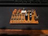
Here it is after I installed new parts:
IMG_1426.JPG
 
I really don't think so. My understanding is that it's just a matter selecting the right bulb so that the dimming behavior is as expected. Actually a 100W bulb is probably ok too.

One option would be to take pictures of all the components and then go ahead and strip and rebuild that power supply board since you have all the parts and have the board loose and accessible. It's just a handful of components. Then see if it solves the voltage problem. (note: others would recommend trouble-shooting first but I'd go ahead and rebuild since this board is so easy and needs to be done anyway - that's just my opinion.)

In case it helps, this is a picture of the PS board from my SX-636 after I stripped the parts off and cleaned up the old glue.
View attachment 1882678

Here it is after I installed new parts:
View attachment 1882680

Wow, looks really nice! I'll probably save the stripdown and rebuild for when I actually have the parts (hopefully Monday), but you may have convinced me to start early ;) May I ask how you're dealing with the wires? Are you planning to just resolder them to the pins when you reinstall? Mine is already a bit messier than yours because some of my wires are already soldered instead of wrapped, and I'm having a bit of trouble getting some of them off. Seems like whoever worked on it previously wrapped the wires around the pins and then used solder to seal it, which is a good idea until you have to take it off again :rolleyes:
 
Sure,
Actually mine is all back together now, and works great.

Some of my wire connections on that board were brittle and broke, so I decided to unsolder all of them and take the board out . . . then I had to solder each back on and it was pretty tight. REally it was a pain! That's not recommended! If you can leave as many wires attached that's definitely better. On the other boards I didn't have to remove the wires and I shouldn't have on this board.

If you are unsoldering something like that I find that solder wick works great, especially with flux on the braid and some good heat. If it's really messy blobs of solder I'd re-do it probably. I 'll try to take pictures of how mine ended up tomorrow. It sure sounds good; I love it.
 
I admit on mine I was soldering on the power supply board a bit past vertical. With some practice you can solder near to vertical. Just don't run too much solder into the joint or it starts flowing down the board. Some units are easy to work on, others more challenging. On some of the old cap coupled Pioneers you have to de-solder a few wires and work the amp card/heat sink assembly out of the chassis to work on them.

I like to use solder wick a lot. A vacuum sucker does come in handy where you have a joint with a lot of solder in it. Wicking you keep those joints hot for a long time. You have to watch a solder sucker near board traces, it can suck them loose too.

These guys are about 45 years old. Some units may look untouched others may have had work done on them. Quality of the past work can vary a lot.

Mine is sounding good, just some problems looks like I need to clean the function selector better. Those can be a problem for dropped channels on several vintage models I have dealt with. Either cleaning of the contacts or those that solder into a board the solder joints needed some rework. Sometimes it takes more than one cleaning effort on the function selector to get them behaving. Tried source into AUX was missing a channel, switching it to Tape 1 both channels were good.

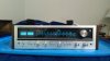
While I work on the function selector with some D100, just switched the workroom system back to the 50 year old SX-1500TD which I admit I like better. The SX-636 a fellow AKer recovered off the junk pile outside a Goodwill, tested and found it crackling, put it on CL cheap as a fix and repair, I bought it and am almost done restoring it. It was in too good of shape to be treated as junk.
IMG_20191007_215018.jpg
 
Last edited:
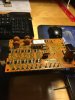
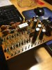
Parts arrived today and the power supply board is rebuilt, with the exception of the D313 transistor which I'm waiting on heat sink compound to swap out. It went pretty smoothly, but a lot of the old caps were definitely leaking something. Some of them seemed to be stuck to the board with a brownish stretchy substance that was coming from the bottom. I was able to pull them off and scrub the residue off the board with rubbing alcohol, and all is well. I did have to unwrap/desolder the wires connected to the board because I wasn't able to desolder/resolder from below the board at an angle. Guess I'm just not good enough at soldering yet! Attached are pics of the rebuilt board. Tomorrow once the compound comes in I'll swap out the last transistor and hook it back up. Hopefully this will fix the voltage problems I was seeing. If it doesn't, would that indicate a problem with the transformer?image.jpg
 
You see the brown stuff in the older stuff holding down the bigger capacitors to boards. Makes it a bit fun removing them, trying to judge when the wires are free of the trace and using enough force to pop the glue. Some of them can be glued down well until it pops you wonder if something else will give.

The cleaning last night now has AUX position letting both channels through. Will have to try the phono section later tonight.
 
I did have to unwrap/desolder the wires connected to the board because I wasn't able to desolder/resolder from below the board at an angle.

That's ok. I think there are pros and cons . . . I thought it was a lot of work to reattach - you'll find out probably! :) You'll know they are well-attached and good connections this way though and it's great for working on it, to have it removed.

Good luck re-soldering! If you have any questions about what pin a certain color wire goes to etc. I'd be glad to check mine, it's sitting right here with the covers off still.
 
Back
Top Bottom