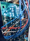
I started a recap job on an SX-650 given to me by my big brother a year ago. It is the version that has IC's in the phono section. The cabinet is in rough shape, but the faceplate is clean and it has all the knobs. This receiver has been worked on before. The power switch had been bypassed with a switch mounted through the top of the cabinet (not where I would put it). I put it on the dim bulb, checked it for DC on the speakers before trying it out. I deoxed the volume and balance pots. Both channels work, but they are noisy. Thankful that the power packs work. If they didn't, I would have stopped there.
I replaced all the caps and transistors on amp board 1 (GWH-101) without issue. I did not replace the 2SA798's - yet. I guess I should at least remove them and test? I do have (4) 992's that match pretty well if I need to replace the 798's. GWR_101 was pretty dirty on the foil side (see Pic). It appears to be a white powder residue. Anybody have any ideas? I sprayed with 91% IPA, but I need to get out the q-tips and wipe it down.
I replaced C23, 24, 28, and 29. All of the caps on the amp boards appear to be OEM as they are all the light blue Nichicons. When I pulled C36 it was a 100uf 16v. The service manual documents it as a 220uf 16v. I don't understand schematics enough to know if the circuit around Q14 and Q15 should have a 220uf or a 100uf. And I don't know if C36 had been replaced. Has anyone run into this on an SX-650?
Lastly, Q5 and Q6 appear to be matched as they have yellow paint on top (see pic 2). The schematic doesn't present them as a normal differential pair. But, should I match any replacements? Pic 2 also shows the empty space for C36.
I appreciate all the help that I received when I recapped my SX-950 a couple years ago (still sounds great) and also the SX-434 that I finished a couple of months ago.
I replaced all the caps and transistors on amp board 1 (GWH-101) without issue. I did not replace the 2SA798's - yet. I guess I should at least remove them and test? I do have (4) 992's that match pretty well if I need to replace the 798's. GWR_101 was pretty dirty on the foil side (see Pic). It appears to be a white powder residue. Anybody have any ideas? I sprayed with 91% IPA, but I need to get out the q-tips and wipe it down.
I replaced C23, 24, 28, and 29. All of the caps on the amp boards appear to be OEM as they are all the light blue Nichicons. When I pulled C36 it was a 100uf 16v. The service manual documents it as a 220uf 16v. I don't understand schematics enough to know if the circuit around Q14 and Q15 should have a 220uf or a 100uf. And I don't know if C36 had been replaced. Has anyone run into this on an SX-650?
Lastly, Q5 and Q6 appear to be matched as they have yellow paint on top (see pic 2). The schematic doesn't present them as a normal differential pair. But, should I match any replacements? Pic 2 also shows the empty space for C36.
I appreciate all the help that I received when I recapped my SX-950 a couple years ago (still sounds great) and also the SX-434 that I finished a couple of months ago.