• The move to the new server is done. There are some software and database maintenance updates in process. This has us passing the hat around to help out. We appreciate any donations. Seriously, even a dollar helps. The payment page may be found here - https://www.audiokarma.org/support.html

SX-727: Mostly done, what next? Bias, Filter Caps, Relay

Christa

New Member
First off - Thank you so much to everyone that helped me along the way. Even if you didn't directly answer one of my threads I have learned so much from reading past threads and everyone has been incredibly helpful and generous with their time. I really do appreciate it.

So, I've got the SX-727 up and running. Its come a long way from the state it was in- originally not working in one channel, scratchy and popping, tuner cord chewed in half and a mouse living in it. So, here's what I've done: I replaced all the electrolytic capacitors on all of the boards with the exception of the fm tuner board. I also replaced many of the transistors known to be problematic and any that I saw that had been from previous fixes. I left the output transistors and the high voltage ones on the AF board alone. I replaced all the zener diodes and added a flyback diode on the protection board. And of course replaced the tuner cord.

I did not replace the big filter caps or the relay. Is that something that I should do right away or wait until they fail?

I also didn't adjust the bias because I have no idea how to do that. It wasn't listed in the service manual. It sounds great - but am I doing damage by not setting the bias?

Also - just want to put this note out there for any novices. I started on this a couple of years ago with only a radio shack soldering iron and a desoldering braid. It was pure misery and was just barely working. I gave up and figured that I just might not have the skill to attempt repairs. At the time I didn't even know what flux was and didn't know that desoldering pumps existed - so I was lacking some pretty basic knowledge. So, this time when I decided to give it another go I watched a bunch of youtube videos, read through a ton of threads here and got some halfway decent equipment - good multimeter leads with grabbers, flux, a good soldering iron, a clip on fan and light and good solder. It as shocking how much easier it was armed with some reasonable equipment. Make this investment before you get started.

The only thing that I felt was on the borderline was the double sided AF board. It was really difficult to work on and I think if I had a real desoldering pump maybe it would have been easier. If I had started on that board I would have given up - luckily I saved it for last so there was no turning back.

Anyway, long winded post, but again, thank you all so much for all the the help. I'm looking forward to tackling another.

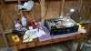
20200121_081511.jpg 20200119_163630.jpg 20200111_190016.jpg
 
Register to hide this ad
Forgetting from your other thread: Did you replace the drive transistor on the protection board? The power supply resistor that gets toasty?
If you don't replace the relay now, you will eventually.
Replace the filter caps. They do after all filter the power going literally directly to your speakers.

If you search AK for SX-727 bias there's some options. I think it's 15-20mV between emitters, but don't quote me.
 
ivandezande - I did replace both of them. I refitted them with the old heatsink, but I have new fancy ones on the way, and I haven't replaced the power supply resistor because I didn't have one, but its on the way as well. I'm going to lift it off the board like you suggested and I also got some fiberglass insulator rope to put on the legs. I think everything is going to be delivered today so I'll fix that up tonight.

I was just anxious to hear the receiver and see if it actually worked. It really does sound great. Clear sound, really warm and bassy (is that a word?) no static or pops, clean controls and it is LOUD.

Thanks again for the help.
 
If you search AK for SX-727 bias there's some options. I think it's 15-20mV between emitters, but don't quote me.

I've got a really basic question - I know which pins are the emitter ones for the left and right side (11 & 13 and 12 & 14) o I just clamp my multimeter leads on both 11&13 and read the voltage while I'm turning the pots? and do I do this on regular power or while I have it on the DBT?

I don't mind going at it with the power off, but I read so many horror stories here of shorting things out that I'm really nervous taking live readings.
 
I'll try to write a summary for you how I did it on my pioneers. Just wait until I have the pictures together.
 
Last edited:
Here is my way, how I did the adjustment of the bias and idle current on all my Pioneer and Yamahas.

As usual, the most important part is always the preparation.
Check the service manual for the values. Unfortunately that part is missing for the SX-727 but I found some information here at AK.

On the unit, there is no need to use it with the DBT if you have checked it before.

You can work with full power, make sure that volume is turned down, input set on aux, no inputs and no speakers connected. The procedure calls for a warmup time of at least 10 minutes until the regulator are settled and stabilized, then make several crosschecks and adjustments.

The measuring pins for bias are different as the one for idle current. So you have four points on every channel. And you adjust these values with two trim pots for each channel.

My best approach was always if I made a drawing for each side with the pins, trim pots and millivolt for the left and right side.
On the SX-727 you adjust the the bias with pins 11 & 13 on left channel, adjusted with the 2.2k pots (VR3) to 20 millivolts between pins 11 & 13.
For the right channel with pin 12 & 14 and VR4. The trim potis sit on the left and right side of the board.

The DC offset is adjusted to 0 millivolt with pin 5 to ground for the left side (with VR1 4.7 kOhm Poti), and pin 6 to ground (with VR2 4.7 kOhm Poti). Both trim potis sit in the middle of the board

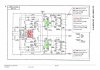
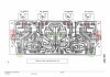
0001.jpg0002.jpg
 
Last edited:
Part two.

So you have now four single adjustment and unfortunately you should make several crosschecks between bias and dc offset.
I found a way to measure always both sides and adjust everything without switching the unit off and changing the leads on the board.
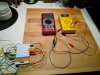
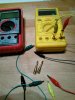
But it only works if you own two DMM! All you need beside the two DMM are 4 banana plugs and 8 test leads (2x 4 colors) with small clamps on each side. Check the picture.

IMG_20200121_223954.jpg IMG_20200121_224045.jpg

I mark on my paper like this for the left side.
Bias: pin 11 red – pin 13 yellow – VR3
Dc offset: pin 5 green – black to ground – VR1

The same colors with the right side.
The unit is still not plugged in to power, continue now and connect the four test leads to the pins according to the plan and make sure that they are not in contact with anything else inside the unit.

Route the leads to the outside in a way, that the open ends of each lead will not get in contact with the others as well. My cheap China made leads are about 2 feet long and that worked very well, but don’t use shorter ones!

Place each DMM on a position where you can easily connect and change the clamps, without having stress on the leads.

Set both DMM to millivolt, I always started with the bias, so the red and yellow leads are the first to be hocked up on the DMM. On the picture you see how I use the banana plugs on the DMM. With this trick you can change the clamps and place them aside while using the other two like green and black.
Having everything rechecked, now you can power up and watch the readings. Only if they are way off start with small adjustments. Then change the leads for the dc offset. It’s up to you how long you let it settle down. Then back again for bias and so on….

Take your time, work save, be careful with the leads AND be absolutely sure that you work on the correct VR !!
If you see now change on the DMM, there is a very high risk that you are on the wrong VR.

It needs only very very small movements. My very first adjustment took my more than 30 minutes because working with millivolts needs experience and patience.

That’s my trick, if anyone has another smart idea, you are always welcome.
 
Last edited:
Nice work! My first receiver was an SX727 and I have warm memories of it, both for the sound and for the aesthetics.

For what it's worth, I think it's okay to leave the existing protection relay and main filter caps in if they aren't causing problems; they are considerably more expensive than most of the other parts you've replaced and may be good for a long while yet. On the other hand I might think differently about it if planning to pass the receiver on to a friend or loved one (in which case I want to be sure it's just as mint as possible) instead of keeping it for myself (since I know I can deal with issues later if/when needed).
 
According to this video (
) you should be able to "access" pin 5 + 6 by using the protector unit board pins to adjust the dc offset. My question is if using pin 1 and 3 is correct as stated in video, or should you be using pin 2 and 4? From my understanding 2 and 4 connect directly to the power amp's 5 + 6. 1 and 3 I think go directly to the speaker relays. Or it doesn't matter?

Thanks.
 
Back
Top Bottom