• The move to the new server is done. There are some software and database maintenance updates in process. This has us passing the hat around to help out. We appreciate any donations. Seriously, even a dollar helps. The payment page may be found here - https://www.audiokarma.org/support.html

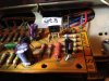
SX-727 Protection Board AWM-027 Question

AJD1964

Well-Known Member
Hello!

I'm putting together a parts list, to primarily do preventitive work on my SX-727. My question specifically relates to replacing the Q3, Q4, and Q6 2SC945 transistors on the AWM-027 board.

Q3, Q4, and Q6 all have an original part description number of 2SC945. I noticed that listed on the common "parts lists" given here in this forum, that Q3 and Q4 are recommended replacement with 512-KSC1845FTA. However, Q6, which is also originally specified as a 2SC945, is listed for a replacement 512-KSC2383YTA.

Why is Q6 listed with a different specification, when originally all 3 transistors called for the same number? I'm guessing some type of improvement? Confirmation on Q6 would be greatly appreciated.

Thanks, Tony.
 
Last edited:
Register to hide this ad
protect circuit transistors, c945 vs ksc2383 vs ksd1616

it's called reverse engineering, and the selections were deliberate.

The 2sc945 in the Q6 position is discharging a 100 uf capacitor through a 22 ohm resistor to turn off the unit. That pulse of energy deposits heat in the transistor's silicon die, and there is a specification of how much heat and how fast, because the thermal energy cannot conduct out fast enough. It's called "Safe Operating Area" (SOA) and the c945 was marginal. the failure of C945 in the circuit is non-intuitive, you just aren't protected - and it's failure is masked because the timing delay part STILL works while nothing else will...

Every time the receiver is turned off, or goes into protection, that c945 gets cooked a LITTLE. Over the years it adds up. Q6's failure rate is lower than the Q7 relay driver's failure rate, but it's cheap insurance.

The ONLY symptom is a "THUMP" at turn-off.

And this stands true for a VAST majority of the Pioneer Silver protect circuits.

AND, as an additional note: IF you encounter a KSD1616xx for that transistor's replacement, don't use it, use the ksc2383, the D1616 was an old choice that a mistake in an old data sheet misled me into choosing it.
 
Last edited:
Thanks Mark!

Thanks for the explanation (and free education)!

I'm not having any problems with this board (yet), but I will refurbish it - and the others as you (Mark) have suggested over the years.

This 727 is my living room daily driver, and it now is beginning to become problematic, in the sense that over the last few days, it has been giving off the random buzz/distorting/static through the speakers.

My plan is to re-cap and re-transistor in this order:
1. Head Amp Unit (to see if that fixes random distortion/static).
2. Power Supply Unit (incl. big main & other random electrolytics).
3. Protection Unit
4. AF Unit
5. Power Amp Unit (Re-Cap only; I found very few threads on changing transistors here - only of there were major problems there first).
6. FM/AM Unit (Repl. Q19 only with 512-KSC2383YTA) - To fix FM Stereo Indicator. Not touching anything else on this board, since all else is good with the AM & FM tuners.
 
I changed the plan slightly:
Re-worked the Power Supply board AWR-011 first. All working good at that point. Just waiting for the heat-sink hardware kits to arrive.

Now - I'm working on the Protection Board AWM-027. I re-capped the electrolytics, and noticed an issue when I powered it up for a test. C3 and C4 show an original specification of 330uf, 6.5v. When I created my list, I bought 470uf, 10v, and installed them. I must have cross-confused something with the old original design, which called for 470uf. Last night, during the initial power-on, protection clicked off normally as expected, but after a minute or so of operation, protection cycled on & off randomly every 20 seconds or so. It did this for approximately the first 20 minutes or so, then appeared to stabilize and now protection seems to work perfect. I ran it 2 hours last night, all OK, and another 2 hours this morning - all OK.

Questions:
1. Did the new electrolytics need an initial break-in or something? Is this to be expected? Protection NEVER gave me issues before this. I have not yet installed the new transistors.
2. Is 470uf too big of a jump from the 330uf design? I have some 330's leftover from another project, so easy quick to swap out if necessary.

Thanks, Tony.
 
Replace with the 330uf's, also set your DC offset and idle current to factory specs, DC could be tripping the relay.

From Mark:
That would be 20 millivolts between pins 11 & 13 on one channel, and 12 & 14 on the other.

that's 20 mA idle current across two 0.5 ohm resistors.


The 4.7k pot is adjusted to 0v:
pin 5 to ground
pin 6 to ground
 
Replace with the 330uf's, also set your DC offset and idle current to factory specs, DC could be tripping the relay.

tsd71 - Yep, exactly, it did not like the 470uf's. Went back into protection immediately after a cold start pwr-on check tonight after work.
330's are in there now - fired up as normal, no tripping relay now. I'll go back & check DC & Idle later, if we all agree is deemed necessary - I need to study that procedure more, since I've never done it. Thanks for the verification on the cap values. Now on to the transistors......
 
also set your DC offset and idle current to factory specs, DC could be tripping the relay.

Something else is wrong.

Going into protection again. Replaced Q7 with the KSC2690AYS, seemed ok. Next, Replaced Q6 with the KSC2383. After changing Q6, the unit will power on, play for 30 seconds or so, then trip into protect. After a 2 or 3 re-starts, it stays in protect until stone cold after a few hours, then repeats the pattern.

Checked DC offset. Got both channels as close to 0mv is I could, at approx. 0.3 to 0.5mv or so. Vr1/Vr2 seem VERY touchy (normal?). They weren't that far off to begin with.

Checked Idle Current (millivolts) Dialed both channels in to 20mv. (I read another post that gave a range of 12-20mv) They were a little off from 20mv, but not much. The Vr3/Vr4 pots seem more "adjusting friendly", and very easy to hit any number between 12-20mv.

Double checked pins on the AWR-011 power supply board; All virtually spot on; Pin2 = 12.5v, Pin5/6 = 30v, Pin7= 36v. All my measurements here were within +/- 1 volt.

Other than double checking for bad solder joints, and voltage checks on the protect board, I think I'm stuck at this point for now.
 
Did you verify the pin positions on the new transistors against the old ones. They will be DIFFERENT. Old one's are BCE or CBE and I've seen CEB or BEC. New ones are ECB or EBC. With the legs pointing toward you , flat side with writing facing UP, Pins are LEFT TO RIGHT. You may have to bend the legs a little to get them in the correct holes. Remember there are 6 ways to insert a transistor. ONLY ONE IS CORRECT. I'd go thru them all again and verify they are right before powering up again.
 
Crazy question:
DC Balance is reading:
.3 to .5v's
Or .003 to .005v's?
The readings could be written as 3mV's or .003v's
If Your DMM is showing ".3" volts, this could be the issue. .3 volts is .030mV or 30mV's.
Just making sure.
 
Crazy question:
DC Balance is reading:
.3 to .5v's
Or .003 to .005v's?
The readings could be written as 3mV's or .003v's
If Your DMM is showing ".3" volts, this could be the issue. .3 volts is .030mV or 30mV's.
Just making sure.

Hi Zeb,
Checked again to be safe - Yes It's mv as in post 7, at least I could swear I put millivolts there.
My meter has auto-scale; Showing -0.15mv on pin 5, and -0.16mv on pin 6 right now, and climbs to approx. +0.5mv but stays under 1mv.
Pin 6 is staying +1.0mv up to +1.5mv, back & forth.
Weird thing is, I just turned it on, for the first time today, and has been playing for over 5 minutes, and hasn't tripped yet.
 
Update - Since it seems ok now, I double checked DC offset and Idle-current (voltage), all still good there. Finished replacing the remaining transistors in the Protection Board, all still seems good after that too. No tripping of the relay anymore. Not exactly sure why it was trippy yesterday. Hopefully this post did not Jinx it.
 
Back
Top Bottom