• The move to the new server is done. There are some software and database maintenance updates in process. This has us passing the hat around to help out. We appreciate any donations. Seriously, even a dollar helps. The payment page may be found here - https://www.audiokarma.org/support.html

SX-727: Rebuild

elvi

Super Member
Will try to actually post updates and pictures.
Thanx to this forum, my upgrade of my SA-6800 with modern Op amps and "Surfboard" adapters was successful.

A bom posted online here for a 727 turned out to be mostly a 737 BOM, so I'm set when one crosses my bench :)
i am now gathering the delta for an order

I will post mine on page one and update it as it evolves.

lets vet some parts. These trimmer pn's look good?

AWH-011-a Power Amp
TRIMMER, VR1 and VR2 semifixed, 4.7 C92-051-0 >652-3386F-1-502LF
TRIMMER, VR3 and VR4 semifixed, 2.2k ACP-001-0>652-3386P-1-222LF

AWM-011 protection

TRIMMER, VR1 semifixed, 100ohm C92-063-0>652-3386F-1-101LF

____________________________________________________________________

BOM, Pending visual inspection of PWB's
 
Register to hide this ad
Paul_Ral
Thank you for the suggestion. Ordered. (literally one day service from Mouser for me :) )
You "Phoenix" rebuild is inspiring. Did you graft the 2500 finals into your new board?
 
OK. Lets get the snowball rolling..


Unit connected to DBT, a 40W bulb was enough to sneak up on the enough voltage for the protection relay to engage.

Off the DBT,
Headphones,small loop antenna connected and on FM.
Solid sound, no distortion in mono: Good stereo, in stereo mode BUT:

Issue 1: Stereo lamp is illuminated at all times, and it varies from a low glow to a strong glow when I would expect it to illuminate (when a stereo signal is present) Lamp is even illuminated when switched to FM Mono mode.

Lets let is sit for a while.

Issue 2. Protection relay drops after a few mins, with low\very moderate speaker load. (headphones, low volume). OK, why I shelved it after obtaining it.

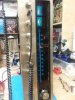
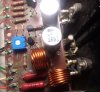
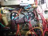
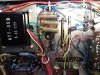
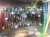
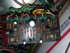
A few photos.
Bottom.jpg
 

Attachments

  • front.jpg
    front.jpg
    112 KB · Views: 19
  • top.jpg
    top.jpg
    113.3 KB · Views: 19
This version is SN: SE3126xx. it is a "E-P" unit, with a green round KW sticker on the back.

Has:
AWM-011 PROTECTION
AWH-011a POWER AMP
AWX-014 CR unit. (Any fidelity gained in bypassing it, as it was intended for FM De emphisis? (By scanning the schematic)
W21-002 HEAD AMP
AWE-015b TUNER
AWR-011a PWR (power Unit)

Open to suggestions around the FM lamp, but I think my 1st steps are a look at the AWP-011a protection board.
(New Omron relay to be delivered tonight)

BOM will be updated where I can. (Cannot edit my 1st post, $$tight these days)
Thanx for suggestions so far,
Blue Shadow;
merlynski
and
paul_ral
 
No, I want outputs for SA-1000 I have restored too but their Hfe are out of specs. I'll go with drivers instead KSA/KSC I used there but I'am fighting with an SX-770 black beauty now. I wish you good luck with your 727!
 
On one of My 828 had the dim lit stereo Issue. I replaced the transistor that controlled the light and it fixed it. The transistor was bleeding voltage through allowing it to light up dimly
 
Update for the day.
AWM-011 PROTECTION

Did a part by part inspection, and see some differences from the BOM
1. Q5. A Mitsubishi A72585g installed. Schematic calls for a 2SA572. Will replace with a KSA992FBU
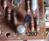
2. R17. 1200 (1k2) installed, Schematic calls for a 1500 (1k5). its connected the the base of Q5, and what looks like a voltage divider of 2 transistors, used as temp diodes? (educate me here if i'm off-base.

Notice, the 2 parts are "related". A running change, as i see zero sign of rework\repair.

I think my 1st action is all caps replacement, and only swapping Q5, for a KSA992F, and test for operation.

Comments?

and, here are a few images. Q5, and then the resistor

Q5-Mits-A725.jpg

R17-1200-.jpg
 
Protection Board complete. (A question on procedure at the bottom of the post)
All E-Caps replaced
All Transistors Except D6 and D9. (Transistors used as diodes, Mitsu VB11-a)


All Parts checked before Install
All parts checked after removal
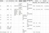
All values tracked in my BOM spreadsheet, in case I get painted into a corner.


Most caps increased their value, but were lossy. (Within spec, but the new parts were dead on their values)
Example:

C3, a 470 16V

capacitance Vloss ESR
513.5uf 2.80% 0.15ohm

Doing full testing on all parts allowed me to locate this little fellow:

Q1. A 2SC983, part of the current detection {Q1/Q2} circuit, measured way out of spec


Q1-2SC983-.jpg

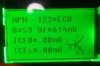
Q2, measured within specs (HFe286, Vf 610)
Q1-Q2 were replaced with a 2383.

pa-prot.JPGAWM-011.JPG

In addition to E-Caps, Transistors, the trimmer was replaced. VR-1. a 100ohm ALPs single turn.
I replaced with with a 652-3386s-1-101lf (thanks to paul_ral)
Pull the alps, measure the wiper and match the setting.

It would have been a tight fit, or I could have extended the trimmer legs, but it needs to face up, and it might be preheated by R-13, 13V Neg rail limiting.
So, I moved it.
R-13-touching.jpg

Out comes R13, and is moved "Down Under"

R13-down-under.jpg


Lots of room now, and no preheating.

after.jpg

No content in the manual around VR-1 adjustment.


Q. I assume TP1 and TP2, DC volts and adjust to zero? Will this value be influenced by awh-011 DC offset?
So, DC offset\Bias 1st, then back to VR-1 on the protection board?


For VR-1 adjustment you must follow AWM-011 board procedure as for W28-007 I found in service manual. Same steps I followed in SA-1000 adjustments
wuJm6kd.jpg
 
Protection Board complete. (A question on procedure at the bottom of the post)
All E-Caps replaced
All Transistors Except D6 and D9. (Transistors used as diodes, Mitsu VB11-a)


All Parts checked before Install
All parts checked after removal
All values tracked in my BOM spreadsheet, in case I get painted into a corner.


Most caps increased their value, but were lossy. (Within spec, but the new parts were dead on their values)
Example:

C3, a 470 16V

capacitance Vloss ESR
513.5uf 2.80% 0.15ohm

Doing full testing on all parts allowed me to locate this little fellow:

Q1. A 2SC983, part of the current detection {Q1/Q2} circuit, measured way out of spec


View attachment 1973549

Q2, measured within specs (HFe286, Vf 610)
Q1-Q2 were replaced with a 2383.

View attachment 1973573View attachment 1973574

In addition to E-Caps, Transistors, the trimmer was replaced. VR-1. a 100ohm ALPs single turn.
I replaced with with a 652-3386s-1-101lf (thanks to paul_ral)
Pull the alps, measure the wiper and match the setting.

It would have been a tight fit, or I could have extended the trimmer legs, but it needs to face up, and it might be preheated by R-13, 13V Neg rail limiting.
So, I moved it.
View attachment 1973598

Out comes R13, and is moved "Down Under"

View attachment 1973602


Lots of room now, and no preheating.

View attachment 1973603

No content in the manual around VR-1 adjustment.


Q. I assume TP1 and TP2, DC volts and adjust to zero? Will this value be influenced by awh-011 DC offset?
So, DC offset\Bias 1st, then back to VR-1 on the protection board?
A drop in trimmer is the 3386F-1-101LF. Looks a lot better than that.

Also you installed the transistor right next to it incorrectly.
 
"Also you installed the transistor right next to it incorrectly"

Sigh.. I pulled it out when I swapped R13 to the bottom. It is a KCS1845, center collector; and I guess I flop flipped it.

Adding a dozen 3386F-1-101LF on my next order.. Thank you on both parts..
 
Update for this week.
Trimmer 3386F-1-101LF; on back-order. I did not drop my order quick enough. Will replace it later.

Power Supply PWB, AWR-011

Did a part by part inspection, no differences from the SM.

E-Caps
Power-ecap.JPG
Silicone


I did not replace the Dual Diode part,pulled and tested. She looked ok.

After:

After-power.jpg

One observation:

Each part was tested after removal, and before replacement


One item of concern?

KSC2073H2TU

Vs

KCS2073TU

SD313, and it’s called for replacement specs were quite difference (KCS2073TU).

I ordered the KCS2073TU, Per posted BOMS. (Not the H2 part)

2SD313 Tested 130 – 160 range

KCS2073 Tested 79-80 range.
power-Silicon.JPG

Per the KCS2073 specsheet (https://www.mouser.com/datasheet/2/308/KSC2073-D-1810349.pdf)

Hfe Classification

H1 40 – 80

H2 60 - 125


Should \ Is KSC2073H2TU a better match? If its causing an issue, I cannot detect it. Brought op on DBT, and now playing through headphones with no issue. (I will not attach speakers until Main caps are replaced, idle\bias set)


Comments?

Up next, Main Caps, and relay
 
Update for this weekend.
Chassis parts this week:
Protection Relay (Swapped new part into the old case)
Main and tuner filter caps
Assorted chassis filtering caps.

Also piggybacked 470uf and 1000uf on the main and tuner caps to bump up their capacity.
(Main to 6900uf, Tuner to 1470uf)
is the following formula "proper" for filter bypass caps? X-Value of filter cap / 1000?
My application: 6800 + 1000 = 6900 \ 1000 = 6.9 uf, min of 63v. I assume a 4.7 would suffice?


Cap list
Chassis--.jpg


C-caps2.jpg C-caps1.jpg
 
Good thread - watching and learning. Can you post your BOM or spreadsheet for AWM-011 protection board? I'm in the middle of sorting mine out and found a very low voltage at the base of Q7 (1.3vdc vs instead of 8.5vdc (schematic is hard to read).

Thanks and I'll be watching with interest and probably following behind you. I was glad to see a current thread on this.

Cheers
 
Last edited:
;)
Look carefully at the posts. You will see the Mouser pns for silicon.
Use UPW series for the E caps, the values are in the schematic. Leave the terta cotta ceramic caps on place. A bump of voltages by the next available is a common practice. I used caps designed for severe duty, leftover from a automotive ECU restoration, but 105f rating will not add much to your rebuild costs.
 
Update this week.
W21-002 Head Amp rebuilt, and bypass caps added to the main filter caps

The main 6800uf filter caps were replaced with Kemet caps PN 80-ALP20A682DD063
Diameter: 40 mm
Length: 55 mm
These are very close to the factory caps in dimension.
Diameter: 41 mm
Length: 60 mm

I also added one 1000uf, a 1uf and a .1uf stacked across each cap lead. bumps the filter to 7800, and adds a little bypass for harmonics. (I'm not to a stage to tell if there is an improvement)

The Head amp was rebuilt with 1845's HFE matched, UPW and Silmic II Ecaps. I did not replace the ceramic and Mylar caps.
The head amp is the Mic and phone RIAA \ Flat preamp.
Note.
the scat denoted 2SC458l, but the board was populated by 2SC131291G.
the typical 2SC131291G HFe varied from a low of 537 and 667.
My 1845' were gain matched and picked as high as my lot allowed. (yes, about an hour of HFe sorting)
the 1845's varied from a low of 386 a high of 420.

(Someone PM me if they have a supply of "E stepping\grade they could be coerced to part with...)

Before
before-W21.png

After
after-W21.png


I am not sure what to tackle next, the Power amp; or strip the front and dive into the Tone\A\F or the tuner.

Suggestions? Leaning towards the Power Amp....

If anyone has a marked Scat, showing the capacitors and transistors in audio path for the AM\FM tuner AWE-015, or has that list I would appreciate it.
 
Back
Top Bottom