• The move to the new server is done. There are some software and database maintenance updates in process. This has us passing the hat around to help out. We appreciate any donations. Seriously, even a dollar helps. The payment page may be found here - https://www.audiokarma.org/support.html

SX-727 Right Channel Drop - Ongoing Headace

ChiefStu

New Member
Problem – right channel drops off/out from preamp R out. Mains in great. Persistent problem still not corrected.

SX-727 produced summer 1973
AF Unit (AWK-010) – from Service Manual
ANP-059 Board label

Obtained a year ago. Was a very clean unit, stored a long time. Initially switches and pots (the latter w/o red Deoxit the 2nd time). Replaced protection relay. Unit has had some board component work over the decades by looking at some poor soldering.

After a couple of months of light use, the right channel would drop totally or cut very, very low volume. Volume pot quick increases to full would correct. First two volume pots worked inconsistently thru the range. As time went on a volume spike would not correct but power cycling would. When the right channel is normal the overall unit sounds great, no scratchy noise, all sources, all front controls work. Right dropout got more frequent first I have:

Replaced ACV-105 volume pot twice, finally have an unmolested one giving smooth range and much more power. Right dropout frequency really decreased. Then it came back and finally died for good. When it drops, it is dead no noise at all. So, on the AF Board I’ve now:

Replaced Q3 & Q4 – originally 2SA725 (-5A or 5b) with Mouser onsemi KSA992FTA
Replaced Q5 & Q6 – originally 2SC1312 (-F or G) with Mouser onsemi KSC1845FTA

Could not find at Mouser replacements for Q1 & Q2 – originally 2SK30A (-Y or GR). AudioKarma suggested replacement was 2SK170 but on other supplier sites the specs were confusing to me, so I chose to wait and ask for advice as to spec and purchase site.

Still have right dropout. As I replaced each transistor, the channels worked. After all four Q's were replaced, both channels ran for a few minutes, then right dropped. Power cycled. Both channels back clean, ran for about 90-min, then right dropped dead. The next day over several attempts, the right comes on and stays at very low, scratchy volume, with balance fully to the right. Any balance to the left masks the right.

Questions:

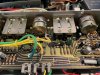
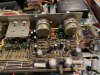
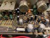
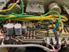
What next? Pictures attached of the board. If ALL the caps were originally blue/grey, some have been done. If they were originally some blue and some all black, then maybe none were ever done. I’d like to really find the right channel issue and clear that, rather than a shotgun approach and risk inducing new problems. When the right channel works its great.

I only have a multimeter, no tone or scope tools. I am not an electronic tech, amateur skills to kind of read the drawings and ID components. Can’t always tell what to measure at what pin. I have done DC bias/offset, they are spot on. I do not intend to restore other units. I had another 727 for 30-years and wanted one back for nostalgia. Besides vinyl I also run a Pioneer RT-1020L R2R into this unit. Now it is a challenge to save this otherwise really nice looking 727. Could I do other parts, later as issues arise, yes. If I do them all now, I risk with my skills making something worse.

Can I trace the circuit flow crudely to where the signal is lost with a multimeter?

Is there another board after, or before, the AF board causing the pre-out right to drop?

Thanks in advance, I would never have gotten this far without Audiokarma!AF Board 2 - 1.jpeg AF Board 2 - 1.jpeg AF Board 2 - 2.jpeg AF Board 2 - 3.jpeg AF Board 2 - 4.jpeg AF Board 2 - 5.jpeg AF Board 2 - 6.jpeg AF Board 2 - 7.jpeg AF Board 2 - 7.jpeg AF Board 2 - 6.jpeg AF Board 2 - 5.jpeg AF Board 2 - 4.jpeg AF Board 2 - 3.jpeg AF Board 2 - 2.jpeg AF Board 2 - 1.jpeg AF Board 2 - 1.jpeg AF Board 2 - 2.jpeg AF Board 2 - 3.jpeg AF Board 2 - 4.jpeg AF Board 2 - 5.jpeg AF Board 2 - 6.jpeg AF Board 2 - 7.jpeg Head Amp.jpg
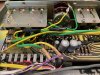
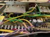
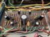
Pictures attached of AF Board before transistor replacement and the head amp board.
 
Register to hide this ad
If I‘m correct, does your last picture show the Head Amp Unit W21?
Did you replace caps and transistor on that board as well?
If yes, can you post new pictures of the W21 Head Amp Board with the new transistor replacement.
One from the part side and a good one from the solder side as well!
 
If I‘m correct, does your last picture show the Head Amp Unit W21?
Did you replace caps and transistor on that board as well?
If yes, can you post new pictures of the W21 Head Amp Board with the new transistor replacement.
One from the part side and a good one from the solder side as well!
No, I have not touched the Head Amp Board. I really dont understand the block flow diagram so I don't know if the fault is on another board in the pre amp section. I can take a pic tomorrow of the solder side
 
I’m not 100% sure, but as far as I understand the main Schematic, both channel from all source run through the Head Amp Unit W21.
By the way, that is the easiest board on the SX-727 to work on and you will be surprised about the new sound if you replace the old 2SC458LG with new 512-KSC1845FTA and new caps as well.
Maybe @markthefixer will help you on that issue.
 
believe it from me, the AM, FM l&r, phono 1 phono 2 have to be amplified and equalized, mic too ALL run through the head amp.
The only one that doesn't is aux.

am, fm have to be amplified and equalized, phono obviously, also mic
so
it's an integral part of the preamp.

pa_200 is correct in every respect... use ksc1845's.. six of them, on the head amp. using low noise UKL caps is a good idea, there are phono signals coming in..
 
Thanks Mark for your verification.

On a SX-727 there are TWO jobs I would always to first, beside lots of other parts.
  • rebuild the Head Amp Unit W21 with new transistors and low noise caps
  • second, add a flyback diode to the Protection Unit, it can be a AWM-011 or the AWM-027 board.
Mine has the AWM-027 and the Flyback diode 1n4004 sits between pin 15 and 14.
Cathode (white ring marking/banded end) goes to Pin15. Pin 14 is to be connected to the other (UN-banded) end of the 1n4004 diode.
20220612_164722.jpg
 
Last edited:
It's real easy to make a signal tracer probe. All you need is a RCA Interconnect cable, and a .1uf 600v film cap. (Orange drop is sufficient in size to grab hold of. Wima's are too friggin small.

1.) wrap one lead of the film cap around the center post of one end of the RCA CABLE. To make it a permanent choice, solder it on. The other lead on the cap is the probe.

2.) take a spare receiver or integrated amp, a pair of headphones, and hook up the other end of the RCA Cable to the AUX input on that amp/receiver. Turn it on and adjust volume low. Plug headphones into spare receiver/amp.

3.) Power up your 727, inject a 1kHz tone (they can be had on the internet) and inject it into the phono input from your phone or laptop. If you have a headphone jack use a 1.8" jack (3.5mm) to a RCA stereo plug. If you have a 12v bluetooth FM transmitter, connect the phone to it, and transmit to the tuner on the 727. (This is better option as you won't overload the EQ AMP and the signal still goes thru the EQ Amp). Turn volume all the way down on phone then advance slightly while you can hear a tone thru your phones.

4.) Each board is essentially 2 channels that are mirrored. Each component on the LEFT Channel has a Mirror component on the RIGHT Channel. Use the schematic and the board drawings. Start at the input and compare tone levels on each lead for each component. when you start from the input, and one side drops off, it's usually on the downstream side of that component. If you can't figure out which side is downstream, mark the offending point on the board drawing. Remember the board drawing is from the SOLDER Side so it's backwards from the top side. If you print it out, put that scan in photoshop, irfanview, or what ever you use for editing and cropping,etc. Do a Horizontal FLIP and then print. The solder side will be the same as your topside.

5.) upload the pic to the forum and we can tell you what part is the offensive one. Best to replace the mirror on the other side at the same time.
 
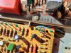
Wow thanks for all the quick assistance! Now I understand better and have a plan! Thanks Larry for the test set-up I have all that but the film cap. When I order that, I can also order the Flyback diode. The Head Amp transistors should be easy to order. As requested attached is a pic of the head amp board solder side...

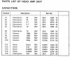
So the question on "caps" when someone says here and elsewhere " do the caps" what type? All caps or just one type? Attached is a pic of the 727 head amp manual Cap's part list.
Just do the 7 Electrolytic caps? or all?
Either way when I go to Mouser, can I just search for the cap description such as "22 10V" ?
When I get cap choices on Mouser, what other specs am I looking for?
I suppose there is a parts list for the had amp board on this web site, but I am leary of trusting that if the mfg names/specs are updated. I don't have the knowledge to know...

For the AF Board if tone testing and rebuilt head amp board takes me back there - same caps question. Does the grey and black electrolytics mean age or just type? If type maybe they are ALL old. Or are the smaller blacks newer and I just do the greys?

Last question, for the AF Board my 727 service manual has a horrible pic of the solder side AF board. The head amp board pic is crystal clear. Anyone have a 727 AF Board solder side pic with readable component ID'sView attachment 2771997 View attachment 2771997
 

Attachments

  • 727 Head Amp Cap List.jpg
    727 Head Amp Cap List.jpg
    116.6 KB · Views: 15
  • AF Board BAck Side - 1.jpeg
    AF Board BAck Side - 1.jpeg
    112.6 KB · Views: 16
Only the electrolytics. Don't change the µF unless you get an advice from the experts, stick to the original µF. Voltage can be higher, 10v up to 16v, 16v up to 25v, 25v up to 35 or 50volt. And look for low noise UKL!
 
AK has been so helpful for me that I try to share what little I can. It certainly doesn't hold a candle to the charity and guidance of Mark & Larry. If they lived closer, I would gladly buy them a 12 pack for the times I've found an answer in a thread they were involved in. Avionic is another great one. He lives in Iowa, so I might actually get to buy him a drink or two some day.
 
If you haven't seen it already, here's a walk through a 727 restoration by Oleg's Vintage Audio that shows each board before & after - https://www.olegvintageaudio.com/2021/01/pioneer-sx-727-receiver-restoration.html
Yes, I have used it on the AF Board work! Fantastic resource, and will be for the head audio board transistor work as to the reversing of the pins needed! On my AF board I found the board symbol for a transistor E leg was wrong and pictures saved the day!
 
Tom Sc; Got Coke's? I don't drink, never acquired a taste for it. Been a designated driver since 18. Now 68. I've been paying it fwd since 2009 on AK.

ChiefStu; On electrolytics, usually anything 2.2uf and less you can sub in a film, provided there is physical room on the board. Some guys do this up to 4.7uf, but physical size of the caps grow exponentially! And they'll last at least until yer Grandkids have gray hair and they're wondering how Gramps fixed it. :naughty::naughty:
 
Yippee success! In short, my intermittent right channel drop on my AF Board was C-14 dropping but some signal spikes could bring it back. C-16 was not cutting out, but very low power. Replaced both and OMG the right channel is now significantly louder than the left!

Thanks to everyone whom assisted and especially for the home built signal tracer from Larry and the PM from a member that sent be a better service manual scan that I was desperate for, as my board view page was too dark to trace part #'s on.

Finding this has taken a ton of hours as it would cut out, run for days, I'd proceed with other replacements, and then finally it really dropped. The 1Hz tone would be really faint at some points and I was starting to despair that I'd have to find a broken trace. But finally I found nothing coming out of C-14. So along with all the signal tracing, I was taking left/right multimeter measures, even though I did not have the proper values, I could see patterns, and also checked all the grounds and pins in/out voltages. So to verify the weak tone drop at C-14 I placed the multimeter on either side of the cap and BOOM it and the right channel snapped to life!

I have learned a ton on reading, tracing and really understanding both the head amp and AF boards. So for a beginner, I feel good I found it and am now going to finish recapping the AF Board, transistors are done. Half the Head Amp board still needs to go - the right side as I could not repair/test it, as the AF board dropped the last time.

A ton of lessons learned and maybe someday I'll write something for newbies, whom can't understand the circuit eletric function design, but can learned to trace and solder properly etc. But here is the LARGE lesson - when a persistent cut out occurs, don't take take easy path advice to "shotgun" replace known problem parts or replace a volume pot without making sure it, and not the circuit PAST it, is the problem. Tone or otherwise trace and when the break is found, then repair, then make improvements. What I have done so far with two caps, four transistors and the head amp have brought this receiver to a much more normal life. I am now in the camp to recap the electrolytics in the signal circuits at least - no point in trying to baby them along.
 
Back
Top Bottom