Some units cleaning the controls can help fix ills. Recently picked up a fix and repair HK 330C listed as no output and cleaning the controls brought it back to life. A guide posted here:
https://audiokarma.org/forums/index.php?threads/the-idiots-guide-to-using-deoxit-revisited.207005/
This vintage Pioneer can have a number of transistors that get flaky with age, particularly in the amp circuit. Got its sibling SX-636 bought untested and cordless cheap they said it was crackling before putting a cord on it replaced six known problem children in the amp section put a cord on it brought it up and sounded great on FM. Usually bad transistors may wait until they warm up, 5-10 minutes after a cold start, before they start acting up.
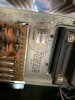
Looking at the schematic of that unit the amp circuit has a number of similarities to the SX-636. The known problem types are the 2SA726 that should be used in the differential pairs and the 2SC1451 in each amp channel. Those I replaced in the SX-636 and it behaved well with the FM tuner. Have a hum with tape and aux inputs that will be diagnosed in the future. The 2SC1451 will stand out it is a metal can transistor that looks like it has a big circular heat sink on it. Both can get very noisy. I used the KSA992 (FBU or FTA - the F is the gain class and BU is loose bulk and TA is on a taped strip) to replace the 2SA726 and the KSC3503 for the 2SC1451. Note the KSC3503 is a TO-126 type so the holes will have to carefully be enlarged to allow the legs to go through the board. You don't want to tear out the foil trace on the back of the board - carefully with a very small sharp drill bit from the foil side is how I approach it.
Have had two units (SX-636, Sansui 771) that had pairs of the 2SA726 at the front of the amp channel heard the 771 it would sound fine cold but after a number of minutes this crackling static type noise would develop and build came to overwhelm the FM tuner output and at a point started triggering the protection circuit cutting output for periods. Replacing the pairs of 2SA726 at the front of the amp circuit fixed the 771 noise issue.
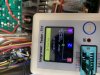
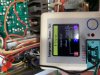
Important if replacing transistors to get the pinouts right - put them in wrong and it may not work or at worst you fry something. Cheap $20 or so transistor tester can help here.
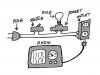
Building a simple dim bulb tester that puts a light bulb in series with the receiver when powering up after repairs can help ensure it is not drawing too much current before putting on regular AC. Mine has saved things from blowing up several times. Put certain transistors in wrong it can try to draw a lot of current. Since the light bulb is in series so if the unit tries to draw a lot of power the bulb stays bright and the voltage the unit sees is reduced. Normally it will brighten up at first as the power supply caps charge and then should dim in seconds. Can leave the switch out and rely on the switch on the unit under test. Using a plug in light socket the setup can be reduced to one receptacle in an outlet box with an input power cord. That requires breaking the links to separate the receptacles in the outlet and then wiring it properly, and maybe marking the light socket one.