• The move to the new server is done. There are some software and database maintenance updates in process. This has us passing the hat around to help out. We appreciate any donations. Seriously, even a dollar helps. The payment page may be found here - https://www.audiokarma.org/support.html

SX-780 blew up a speaker!

naterofsask

New Member
Something in my dang SX-780 failed and took out one of my Dynaco A-25s. I am less than impressed!

I thought these receivers had a protection circuit to prevent this from happening. There is now 41.6v reading on the right channel output.

This receiver has some sentimental value to me and I'd really like to get it working again but have no idea where to begin the repair process. Where should I start?

Thank you!
 
Register to hide this ad
It may have been replaced with a counterfeit part, or it may be a newer revision. Replace it and move on. Check out the protection circuit, it should have opened the relay. Maybe some idiot defeated it or the relay could be welded closed.
 
Left one is a modern fake. I would be worried about the state of your relay and protection circuit. The protection circuit is supposed to prevent speaker damage, so I am surprised that that was able to happen.
 
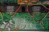
Is this the protection circuit area?

index.php


Yes, that is the general area of the protection circuit. Above the board and along that row of pins should be the PA3004 linear (SIP) IC. The solder connections to some of its pins are a bit suspicious.

The first items to check might be R330 and R331.
 
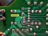
Now you're making headway. We need to find out why the protection circuit is not satisfied, and can only surmise why someone jumped those transistor leads rather than repair the actual problem.

Unfortunately as a result, you now may have a cooked speaker. Hopefully the SEAS TV-EW driver is intact and only a crossover connection failed, but I have reservatons.

post-102007-1153915403.jpg
 
It would be good to begin with measuring the resitance through each output module. Test the resistances between Pins 2 & 3 ans also between Pins 8 & 9 on each module. Chances are that you will find one or both of them at relatively low resistance.

@merlynski has gone to great lengths describing the troubleshooting procedures several times. https://audiokarma.org/forums/index...ng-high-dc-offset.851352/page-3#post-12512551

Begin there, and please report the results of your testing. It should be possible to restore the unit with the new modules you mentioned building and possibly a few other random repairs. However, it will be good to perform diagnosis before the new/good modules are in place to minimize risk of damage.
 
Apologies for the delay! It took me a while to get resistors, solder wick, and proper probes for my meter.
Here are the results of measuring the pins after installing 1k resistors.

1 -4.23v
2 -41.9v
3 .009v
8 .006v
9 41.8v
0 4.27v

1 -4.15v
2 -41.9v
3 .014v
8 .011v
9 41.9v
0 4.03v

Resistance between 2&3 fake: 0.2 ohm
Resistance between 8&9 fake: infinite

Resistance between 2&3 factory: infinite
Resistance between 8&9 factory: infinite
 
Last edited:
Those voltages look pretty good. You may have dodged a bullet and only cooked the output module.

Now we need to establish what is happening in the protection circuit. With the resistors in position and the unit turned on for your voltage measurements, did the protection relay close?
 
That's within the range of acceptable. The important thing is that it closes. C317 sets the time base for delaying the relay on power-up.

If you can access the protection circuit area safely, a few measurements there could completely clear any questions. Measure the DC voltages on Pins 1, 4, and 6 and AC voltage on Pin 7. It will be safer to test the voltage on other components, away from the PA3004 IC due to the tightly packed pins. For example, Pin 1 voltage can be measured at the emitter of Q25 or Pin 38 on the AF board. Pin 4 DC voltage can be measured at R325, and Pin 6 voltage can be measured at R323/R324 junction. Similarly, the AC voltage can be measured at the R319/320 junction. Check each of these as the unit is being powerd on. The voltages should all stabilize within 2-3 seconds.

If all that checks out, you probably have a correctly functioning protection circuit and that will allow you start replacing modules.
 
Back
Top Bottom