• The move to the new server is done. There are some software and database maintenance updates in process. This has us passing the hat around to help out. We appreciate any donations. Seriously, even a dollar helps. The payment page may be found here - https://www.audiokarma.org/support.html

SX-780 Bright bulb on DBT - Looking for help...

dibmem

AK Subscriber
Subscriber
Background: SX-780 blowing fuses. No relay click.
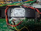
Opened it up to find a .22 Ohm resistor replaced and lots of burn marks from previous repair attempt.

Current status: I have pulled the STK-0050 out of circuit (it may or may not be functional) and I have aftermarket (Chinese) STKs ready to install.
Installed TWW5JR20E-ND in R265 and R263, per other threads on AK.
DBT with 60 watt bulb is BRIGHT, indicating faults elsewhere in circuit.

I'm attempting to read voltages, but they are extremely low.
(Am I doing this right? Cen-Tech P37772 MM set to DC 20 V - chassis ground. Positive probe insulated except for very tip to eliminate shorts.)
Pin 16 = 0.29V
Pin 15 = -0.28V

Other threads state the following:
Measure main pcb pin 16, should be +40vdc: 0.29V
Measure main pcb pin 15, should be -40vdc: -0.28V

I've repaired the via for the R265 and soldered the leg to the pin 3 pad, avoiding the compromised via - tested continuity between pad and pin 3 - all good.
As far as solder work and replacing parts goes, I'm capable. Troubleshooting is still new... Where do I start on this SX-780?
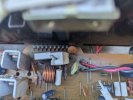
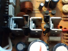
Wrong Resistor.jpgOK Resistor.jpgPack Removed.jpgVia repair.jpg
 
Register to hide this ad
I wouldn't fix it I would restore or rebuild it . You took out the output modules so rebuild the power supply , all new e-caps , remove and diode check or replace all transistors, new bridge rectifier. Test with DBT and check voltages , all good, move to the next board, no good ,disconnect PS from rest of unit DBT test again.
 
Last edited:
Check power supply voltages. The regulators have a habit of getting too hot and lose the solder connection to the board. Reflow the solder on them all.

The three of them need more heatsink. Be sure the added heatsink don't short to one another. I bent the fins out so they don't.

IMG_20210419_105838583.jpg

1781044353544.png
 
Last edited:
@kwayde said:
Check power supply voltages. The regulators have a habit of getting too hot and lose the solder connection to the board. Reflow the solder on them all.

The three of them need more heatsink. Be sure the added heatsink don't short to one another. I bent the fins out so they don't.
:thumbsup:

IMO instead of reflow it is best to totally remove solder from joints that have been compromised by high heat and start fresh.

Extra heatsinks are a good idea.
 
Last edited:
I wouldn't fix it I would restore or rebuild it . You took out the output modules so rebuild the power supply , all new e-caps , remove and diode check or replace all transistors, new bridge rectifier. Test with DBT and check voltages , all good, move to the next board, no good ,disconnect PS from rest of unit DBT test again.
Yes, I would also restore it to last 20+ more years. I would not get 'Chinese" STK's at all. I suggest you obtain new and reliable STK's replacement from @rcs16 per the link below.

STK-0050 replacement for SX-780 and others
 
I’ve built 3 sets of these so far and they work great!
This is an amazing STK replacement. I have a JVC JA-S44 that uses two original STK-0050s; they are fine. Otherwise, I would definitely build the kit from @rcs16 you are showing. I saw XrayTonyB building them years ago. Also, I would love to fully restore an SX-780 with brand new capacitors, power supply components, relay, STKs, etc., but I don't have the availability & space anymore. I saw on YT people restoring or replacing the wooden case of the Pioneer SX series, but I am not equipped for that challenge and would have to outsource the woodworking.

Upgrading the STK-0050 Amp Module in a Pioneer SX-780
 
Thanks for the input on the STK modules - I'll read up on them. :)
In the meantime, here's my measurements:

Q25 E = 0.25, B = 0.70, C = 1.41
Q19 E = 1.05, B = 1.55, D = 1.55
Q20 E = -1.01, B = -1.57, C = -1.57
I'm going to pull these and measure them out of circuit with my Peak DCA55 (which hopefully will tell me which ones are shot).

Pin 16 = 0.29
Pin 15 = -0.28

Can someone explain (like I'm five) why my readings are so low?
(Cen-Tech P37772 MM set to DC 20 V - chassis ground. Positive probe insulated except for very tip to eliminate shorts)

Side note for the interested: I'm trying to work through troubleshooting this unit rather than do buy a kit, pull everything out / replace it. It might not be the fastest way to get it working, but I enjoy the process and the reward of bringing broken / dead equipment to life.
Fuses all good?

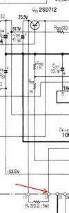
For Q25 go back to the large 220 ohm resistor R1 mounted on the heatsink and confirm that you have about +50 volts at pin 13.

If you do then measure the voltage from across the resistor (pin13 to pin 12) if all is well you should have about 25 volts across it.

If you have the full 50 volts across it then there is a short downstream of pin 12.

For Q19 and Q 20 you need to measure the voltage on both sides of R317 and R318 to confirm you have proper voltage coming in and the resistors are good.


780q25.jpg
 
4A / 250v fast blow main fuse installed, 2A / 250V (fast) and 1A / 250V (fast - two) fuses all in place - continuity confirmed on all.

Pin 13 = 1.55v
between 12 + 13 = 0.13v
Pin 12 = 1.4v

R137 top = 1.54v (nearer base of Q19 - notes for myself)
R137 bottom = 1.53v (connected to collector of Q19- notes for myself)
R138 top = 1.56v (near Pin 22- notes for myself)
R138 bottom = -1.55v (connected to collector of Q20- notes for myself)
 
Last edited:
Bad power switch possibly. Do the dial lights come on?

Check the AC voltage across pin 19 & 20 and across 17 & 18.

Danger Below.. Checking live AC wall voltage in next steps be very careful. o_O

If 17 & 18 and 19 & 20 are both missing check the AC voltage across the switched outlet.

Alternately you can use a small table/desk lamp or radio or any low power draw AC powered device to check the outlets.

If there is no AC voltage at the switched outlet check the unswitched one.

if the switched outlet is dead and the unswitched one is alive then the power switch or the wiring is faulty.


780ps2.jpg
 
Last edited:
No dial lights at power on.
Between 19 + 20 = 4.01v AC
Between 17 + 18 = 2.35v AC

Switched = 5.28v (top) / 5.27v (bottom) = 6.88v between
Unswitched = 1.18v (top) / 1.18v (bottom) = 6.89v between
(Cen-Tech P37772 MM set to AC 20 V - chassis ground. Positive probe insulated except for very tip to eliminate shorts)

The power switch stem was bent when I bought it, possible / likely damage? Power does seem to engage / disengage when I switch it on and off.
 
Last edited:
No dial lights at power on.
Between 19 + 20 = 4.01v AC
Between 17 + 18 = 2.35v AC

Switched = 5.28v (top) / 5.27v (bottom) = 6.88v between
Unswitched = 1.18v (top) / 1.18v (bottom) = 6.89v between

The power switch stem was bent when I bought it, possible / likely damage? Power does seem to engage / disengage when I switch it on and off.
You are setting your meter for AC voltage, correct?

For the unswitched outlet to be dead implies that you have an open circuit in the power cord somewhere.
As you can see in the schematic in my previous post the power cord connects directly to the unswitched outlet.
 
Confirmed meter set to AC voltage, per the manual.

That's what I thought I was seeing on the schematic - unswitched outlet should be wall voltage, right? (Still learning)
I was experiencing some odd behavior when I was turning it on and off - wouldn't turn on intermittently. I'll check my DBT setup and examine the power cord carefully.
 
I just plugged it into the wall, bypassing the DBT and I'm getting 40v +- on pins 15 + 16. Panel lights on and working.
The 4A fuse just cooked, but I have a bunch of them on hand, so that's not a problem.

Direct to wall:
Switched = 0v
Unswitched = 120v

Okay, maybe I'm not using the right size bulb in the DBT? (I have plenty to pick from)
The 60 watt bulb I was using died - likely that's what I was fighting with?
[My best guesses after looking at the service manual.]

New numbers:
Q25 E = 13.55v, B = 14.23v, C = 28.6v
[This one is no good? Replace?]
Q19 E = 40.2v, B = 40.8v, D = 50.5v
Q20 E = -40.3v, B = -41.0v, C = -52.4v

Pin 16 = 40.6v
Pin 15 = -40.4v

Pin 13 = 51.5v
between 12 + 13 = 22.8v
Pin 12 = 28.6v

R317 top = 51.6v (nearer base of Q19 - notes for myself)
R317 bottom = 50.5v (connected to collector of Q19- notes for myself)
[R317 seems to be OK?]
R318 top = -53.3v (near Pin 22- notes for myself)
R318 bottom = -52.3v (connected to collector of Q20- notes for myself)
[R318 seems to be not OK - collector voltage isn't right?]
 
Last edited:
Confirmed meter set to AC voltage, per the manual.

That's what I thought I was seeing on the schematic - unswitched outlet should be wall voltage, right? (Still learning)
I was experiencing some odd behavior when I was turning it on and off - wouldn't turn on intermittently. I'll check my DBT setup and examine the power cord carefully.
Yes, both the switched and unswitched outlets will show wall voltage under normal operation..

I just plugged it into the wall, bypassing the DBT and I'm getting 40v +- on pins 15 + 16. Panel lights on and working.
The 4A fuse just cooked, but I have a bunch of them on hand, so that's not a problem.

Direct to wall:
Switched = 0v
Unswitched = 120v

Okay, maybe I'm not using the right size bulb in the DBT? (I have plenty to pick from).
I have a variac we can use, if that'll help.
That is good and bad news. It seems your DBT might not be working? Is the bulb good? I personally use a 75-100 watt bulb for most everything.

+ and - 40 volts on pins 15 & 16 is good, are any of the STK packs installed, I know you had one out earlier.

Blowing the 4 amp fuse is bad, and it is a problem. You don't want to just keep putting fuses in or you run the risk of burning something else up.
The DBT should keep the fuse from popping, and give you a visual indication of high current draw so you can shut it off before the fuse blows or other damage occurs.

Next steps would be be to figure out the DBT issue.

In certain instances I use a variac, but for most things the DBT is a better choice.
Or plugging the DBT into the Variac so you still get the current limiting effect of the light bulb.
 
One STK is out (left channel?). The other is still in. I can pull the other too.
60 watt bulb died - maybe it was on the verge of death when I was measuring everything. I edited my previous post with new numbers. I'll put a 75 watt in and see if things measure as they are supposed to.

Edit:
100 watt bulb in - DBT confirmed working. Getting 120V AC at unswitched outlet. 0v AC at switched.
The other numbers are lower overall, but the panel lights are on and I think we can move forward.
 
Last edited:
One STK is out (left channel?). The other is still in. I can pull the other too.
60 watt bulb died - maybe it was on the verge of death when I was measuring everything. I edited my previous post with new numbers. I'll put a 75 watt in and see if things measure as they are supposed to.

Edit:
100 watt bulb in - DBT confirmed working. Getting 120V AC at unswitched outlet. 0v AC at switched.
The other numbers are lower overall, but the panel lights are on and I think we can move forward.
:thumbsup: With the panel lights on we have power through the transformer. How bright is the bulb?

Something is wrong in the switched outlet. Maybe not making good connection with the meter, ignore for now.

Lets go back to my post #9 and see what the voltages are now.

For Q25 go back to the large 220 ohm resistor R1 mounted on the heatsink and confirm that you have about +50 volts at pin 13.

If you do then measure the voltage from across the resistor (pin13 to pin 12) if all is well you should have about 25 volts across it.

If you have the full 50 volts across it then there is a short downstream of pin 12.

For Q19 and Q 20 you need to measure the voltage on both sides of R317 and R318 to confirm you have proper voltage coming in and the resistors are good.

You can Look for +39.5 at the +side of C307 and -39.5 at the - side of C308.

You can also check for +21.5 on the end of R301, +23.7 on the end of R302, -23.7 on the end of R304, and -18 on the end of R303.


1781200203892.png
 
This is weird, but I took a little time away from this and now it's acting like there's no short. DBT is dimming to near nightlight level with 100 watt bulb.
Switched outlet is around 109v AC when the switch is engaged / 0v AC when off (seems right?). Unswitched is at line voltage 120V AC.
I'll do more measurements in a moment - thanks for helping me through this. Thought I was losing my mind earlier.
You are welcome. Actually the switched outlet should be almost exactly the same voltage as the unswitched. You may very well have a high resistance contact in the power switch, which is not unheard of. I don't recall if the 780 switch is easily repairable/cleanable. It takes more than a squirt of DeOxit to clean them.

Search here and on your fave search engine and see what comes up.
 
Back
Top Bottom