• The move to the new server is done. There are some software and database maintenance updates in process. This has us passing the hat around to help out. We appreciate any donations. Seriously, even a dollar helps. The payment page may be found here - https://www.audiokarma.org/support.html

SX-780 Left Channel Bad

bzenic

Active Member
After I brought a SX-780 home the relay would not engage at all.
I've refreshed solder on Q25 and the relay started to engage and was getting FM working on the right channel and crazy loud whistling sound on the left. The whistling would start immediately after turning it on independent of the volume control.
Well, after a few switchings off/on something probably blew off and now I have this situation:
After turning the receiver ON I again don't get relay engaged.
I measured the voltages on outputs on pins 25 (40 mV) and 27 (about 14 V !)
Apparently something really bad happened on the left channel.
I found out that when I remove the left STK (looking from the component side) I get FM playing ok on the right channel, volume control works.
What would be the next move, what measurements should I try?
 
Register to hide this ad
Just for shitz-n-grins I paraphrased your question and posted to the ChatGPT AI website www.chat.openai.com to see what kind of response I would get. I was surprised with the response was actually fairly accurate and straightforward. I think I will start a thread on this and see if others want to add their questions and the ChatGPT AI responses. Could be a fun thread to play with, perhaps in the DIY page.

Edit: I should state that using ChatGPT is no replacement for proper technical expertise, training and most of all, years of experience.

See below:

Paraphrased question posted on ChatGPT:
After I brought a SX-780 home the relay would not engage at all. I found out that when I remove the left STK output transistor pack the Right channel works. What would be the next move? What measurements should I take?.​


ChatGPT Response:
It seems like you are experiencing an issue with your Pioneer SX-780 receiver, specifically related to the STK output transistor pack for the left channel. To troubleshoot this issue, follow these steps:
1 Visually inspect the STK output transistor pack that you removed for any signs of damage, such as cracks, burns, or bulging. If you find any physical damage, consider replacing the pack.
2 Check for any damaged or burnt components on the amplifier board, particularly around the left STK output transistor pack area. This may include resistors, capacitors, diodes, or other components. Replace any damaged parts you find.
3 Check for any cold solder joints, cracked traces, or lifted pads on the PCB around the STK output transistor pack. If you find any, reflow the solder or repair the traces as needed.
4 Test the STK output transistor pack itself. You can do this using a multimeter or component tester to check for short circuits or open circuits between the pins. If you find any issues, replace the STK pack.
5 Check the bias and DC offset of the left channel. The service manual for the Pioneer SX-780 should provide the recommended voltage levels. If the bias or DC offset is out of spec, adjust it according to the manual.
6 If everything seems fine but the issue persists, it's possible that the problem lies elsewhere in the circuit. This could include the preamp, power supply, or protection circuit. Consult the service manual and schematic to further troubleshoot these areas.
Remember to take the necessary safety precautions when working with electrical equipment, including disconnecting the power and discharging any capacitors before you begin. If you are not comfortable or experienced with electronics repair, it's always a good idea to consult a professional technician for assistance.
 
Last edited:
Thank you @jd3rdcoast, for doing that.
As an update I fixed the receiver, it turned out to be a burned (and open) resistor R259 (200 Ohm) it measured in MegaOhms.
I replaced it with 150 Ohm resistor I had, adjusted the DC offset to 0. and it's working great.

Bottom line:
Always first refresh solder (at least) on Q25 when you start fixing SX-780.
 
Thank you @jd3rdcoast, for doing that.
As an update I fixed the receiver, it turned out to be a burned (and open) resistor R259 (200 Ohm) it measured in MegaOhms.
I replaced it with 150 Ohm resistor I had, adjusted the DC offset to 0. and it's working great.

Bottom line:
Always first refresh solder (at least) on Q25 when you start fixing SX-780.
Just out of curiosity, did you look up R259 value using the resistor color code calculator?
 
It's listed on the schematic as 200Ω. 1/4W. I find that calculator coding that pioneer supplies is overly complex and I'm confused as a 2nd Lt. Marine in a Corn maze with 1 stalk. Resistor color code is easier (B-B-R-O-Y-G-B-V-G-W) "Bad boys ravage our young girls, but Violet gives willingly". (Black, Brown, Red, Orange, Yellow, green, blue, Violet, grey, White.)

Here's the info on the one I use now......
ScreenHunter 749.jpg
 
It's listed on the schematic as 200Ω. 1/4W. I find that calculator coding that pioneer supplies is overly complex and I'm confused as a 2nd Lt. Marine in a Corn maze with 1 stalk. Resistor color code is easier (B-B-R-O-Y-G-B-V-G-W) "Bad boys ravage our young girls, but Violet gives willingly". (Black, Brown, Red, Orange, Yellow, green, blue, Violet, grey, White.)

Here's the info on the one I use now......
View attachment 2841121
The reason I ask is because I have my own thread for a 780 going on AK now too. MTF referred to the calculator from DigiKey to check it. The DigiKey calculator is the one I have used for awhile now. That resistor is listed as 200 ohm in the SM but the one I pulled measured 150 ohm and the calculator showed it to be 150 ohm. Apparently some have a 150 ohm and others have the 200 ohm resistor. As he said it could have been a design change.
 
I didn't look at the color coding, it was listed on schematic as 200 ohm and I didn't have 200 ohm resistor so I just used a 150 ohm I had.
You guys now reminded me to check and measure the value of the analogous resistor R260.
 
I just repaired 2 780s with the same issue, both were 150 ohm. However, the older ones tend to use the 200 ohm... least from others I have seen. So absolutely check the band codes.
 
What was that issue exactly?

Bad stk and burned R260.

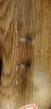
When the stk on these blows, it tends to take out the 1885 transistor that makes up the stage one bank with the 2 others and burns R260. Always been right side for me that blows. Both units the 1885 shorted, but one of them had been previously serviced. Attached is what I found in the right compared to left. No idea what that transistor is. Btw, band code is brown, green, brown. Bad image. Ended up rebuilding both sides.
 

Attachments

  • 20230311_165200.jpg
    20230311_165200.jpg
    90.6 KB · Views: 15
Discrepancies between manual and actual unit. Go with value on Unit. None of the manufacturer's did much to document (if anything) minor running line changes.
 
Back
Top Bottom