• The move to the new server is done. There are some software and database maintenance updates in process. This has us passing the hat around to help out. We appreciate any donations. Seriously, even a dollar helps. The payment page may be found here - https://www.audiokarma.org/support.html

SX 780 No output.

Hawkibig10

New Member
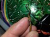
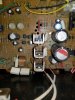
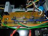
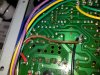
Hello. I have power to the face lights, source light and tuning needle. No output from speakers. I checked the basics and then found this. In the pics are a brown wire that appears to have heated up/shorted out. Bare wire exposed and melted shield. The wire goes back to the transformer. There is a discolored row of pins on the pc board adjacent to the brown wire. Also a pic of the other side of the pc board. I'm guessing it blew a component on the other side of the pc board. Should I take it to a pro, drop it in the river or attempt to troubleshoot myself? Any insight would be greatly appreciated as electrical is not my specialty. 20180125_203429.jpg 20180125_203429.jpg 20180125_203743.jpg
 

Attachments

  • 20180125_203439.jpg
    20180125_203439.jpg
    131.8 KB · Views: 33
  • 20180125_211525.jpg
    20180125_211525.jpg
    66.6 KB · Views: 39
Register to hide this ad
whats on the other side of the soldered traces where the wire melted?
Never mind I saw the thumbnail.
Checking............
 
Last edited:
It looks like it could of fried the rectifier for the protection circuit.
It might be limited to the diodes in the bridge.
Also:
There is a fuse, FU2 on the fuse board that is the protection for that circuit. Check it first. If open replace it and DBT it. Check for a dim bulb and if the set responds. If it does, check the amp settings for proper voltages.

You will have to build a DBT (Dim Bulb Tester) before you begin any work. And check out the other components in the circuit. It looks like diodes D8, D9, D6 and D7.
It maybe an easy fix. Four diodes :dunno: or a fuse, lets hope so.

If the fuse was good:
Plug it into the DBT with a 75 or 100 watt bulb and check for a dim bulb. If dim, check the power supply voltages.
If the bulb is bright and remains bright shut it off quickly. Tackle the rectifier by replacing the diodes and checking the other components. Transistors, resistors and the other diodes in the circuit.
Tip: If only a few diodes of the four are damaged you might get by with only the rectifier diode replacement. Then DBT it - see what happens.
 
Last edited:
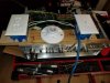
Thank you for the insight. I built my dbt and repaired the brown wire that was compromised. I will continue with the steps you laid out for me. I will likely need a little help down the line. I downloaded the service manual and schematics. I can read many types of blueprints but electrical schematics might as well be written in Mandarin. I am willing to do research and homework to achieve a favorable outcome. I will keep you posted.20180127_193406.jpg
 
There are two rows of DIODES. One row will get replaced with 1n4007's and the other with 1n5408's. (I know......These diodes are rated for 1000v so it's a bit of overkill.)

Top of AREA INVOLVED. Next to the Heatsinked Voltage Regulators are resistors in fiberglass sheath's. Check and replace if bad. Check out of circuit(Lift one leg out)! This one has been uprated and recapped. The DIODES are 1n4007(smaller) and 1n5408's (larger).
780-790  Front Left modded.JPG

It looks as if your DBT needs additional work. Take and cut one of the wires from the switch to the outlet and connect the ends to the Bulb socket. Then it'll work as described. Unless this is a before finished pic, in which case disregard the suggestion.
 
It looks like it could of fried the rectifier for the protection circuit.
It might be limited to the diodes in the bridge.
Also:
There is a fuse, FU2 on the fuse board that is the protection for that circuit. Check it first. If open replace it and DBT it. Check for a dim bulb and if the set responds. If it does, check the amp settings for proper voltages.

You will have to build a DBT (Dim Bulb Tester) before you begin any work. And check out the other components in the circuit. It looks like diodes D8, D9, D6 and D7.
It maybe an easy fix. Four diodes :dunno: or a fuse, lets hope so.

If the fuse was good:
Plug it into the DBT with a 75 or 100 watt bulb and check for a dim bulb. If dim, check the power supply voltages.
If the bulb is bright and remains bright shut it off quickly. Tackle the rectifier by replacing the diodes and checking the other components. Transistors, resistors and the other diodes in the circuit.
Tip: If only a few diodes of the four are damaged you might get by with only the rectifier diode replacement. Then DBT it - see what happens.
There are two rows of DIODES. One row will get replaced with 1n4007's and the other with 1n5408's. (I know......These diodes are rated for 1000v so it's a bit of overkill.)

Top of AREA INVOLVED. Next to the Heatsinked Voltage Regulators are resistors in fiberglass sheath's. Check and replace if bad. Check out of circuit(Lift one leg out)! This one has been uprated and recapped. The DIODES are 1n4007(smaller) and 1n5408's (larger).
View attachment 1099724

It looks as if your DBT needs additional work. Take and cut one of the wires from the switch to the outlet and connect the ends to the Bulb socket. Then it'll work as described. Unless this is a before finished pic, in which case disregard the suggestion.
Do you see the black wire coming from the switch to the light? Then the to the outlet, then from the other side of the outlet back to the supply. The green wire is from the outlet ground back to the green wire in the power supply cord. It may not be needed. I tested the dbt and when I flipped the switch nothing happened. Then I used a jumper wire and stuck it in the outlet and the bulb lit up. I think this is the desired result.
 
It looks like it could of fried the rectifier for the protection circuit.
It might be limited to the diodes in the bridge.
Also:
There is a fuse, FU2 on the fuse board that is the protection for that circuit. Check it first. If open replace it and DBT it. Check for a dim bulb and if the set responds. If it does, check the amp settings for proper voltages.

You will have to build a DBT (Dim Bulb Tester) before you begin any work. And check out the other components in the circuit. It looks like diodes D8, D9, D6 and D7.
It maybe an easy fix. Four diodes :dunno: or a fuse, lets hope so.

If the fuse was good:
Plug it into the DBT with a 75 or 100 watt bulb and check for a dim bulb. If dim, check the power supply voltages.
If the bulb is bright and remains bright shut it off quickly. Tackle the rectifier by replacing the diodes and checking the other components. Transistors, resistors and the other diodes in the circuit.
Tip: If only a few diodes of the four are damaged you might get by with only the rectifier diode replacement. Then DBT it - see what happens.
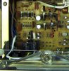
When I tested the reciever with the dbt and 75 watt bulb, it started dim, then went and stayed very dim. Can you elaborate on how to check the power supply voltage. I also included a pic of the fuses. 20180128_132057.jpg 20180128_132057.jpg
 
Do you see the black wire coming from the switch to the light? Then the to the outlet, then from the other side of the outlet back to the supply. The green wire is from the outlet ground back to the green wire in the power supply cord. It may not be needed. I tested the dbt and when I flipped the switch nothing happened. Then I used a jumper wire and stuck it in the outlet and the bulb lit up. I think this is the desired result.
Can you elaborate on how to check the resistors. Also, where do I purchase diodes if and when necessary? Thanks again to all that are helping me. Greatly appreciated!
 
Fuses Good?
They look good but you should check them in Ohm's mode on the DMM to be sure (Power off). Or check for AC on either side of them, with the set powered up, on the DBT of course.
 
Sorry, the Black wire was camoflague'ed by the dark background. I had to lighten up the pic to see it. IF all the fuses check out on the DMM and the DBT shows a large dimming about 1-3 seconds after power switch is thrown, you've probably got an open in the Voltage regulators (3 transistors in a row) or a bad solder joint there or on the diodes. I've seen a shitpot of 780/790's that don't work and all I had to do to get them running was to finish desoldering the diodes and the regulators, test them and resolder or run jumpers and solder them back up. Which is the big reason for the heatsinks on the Voltage Regulators now. See my Pics above in previous thread.

Set your DMM now to DC VOLTS(200 or higher or Auto if it has that function). Clip the black probe to the chassis (any clean bright part). With the RED PROBE, (INSULATE ALL BUT THE EXTREME END OF THE PROBE to remove chances of shorts or scivvie marks in your shorts when the probe slips(it does and will happen to all of us at one time or another) Check for voltages on the diodes. Follow the schematic. If you have voltages on all the diodes the next thing to check is the Voltage Regulators. RE-DO the SOLDER POINTS 1st! Then report back with Results.
 
The Brown wire that got crushed is from the CENTER TAP of the GREEN WIRED section of the transformer. It's set up as a GROUND per the schematic. So this isn't your problem except if it got separated. Cut out the bad section and solder the ends, cover with 2 layers of heatshrink tubing.

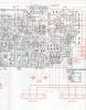
It looks like the diodes need to be DE-SOLDERED, and resoldered. The joints are really crummy. Do both sets. Then find the Regulators (Q19, Q20, and Q25). Below is a partial screen shot of the full board and shows the layout of the power supply so you can find the parts.

The diodes are replaced with 1n4007 and 1n5408 rectifier diodes. Mouser and or Digikey has them. Just type those designation in for the diodes.
Do a 6 way test on the transistors as noted in this thread.... http://audiokarma.org/forums/index.php?threads/bipolar-junction-transistor-testing-basics.43186/
If any test bad we'll get you numbers for uprated replacements. None of the original transistors are made any more so everything is replacement FAIRCHILD or OnSemi.

Resistors are available @ Mouser or Digikey also.
780 board diagram power supply.jpg

Download this and it should expand to original size. NOTE!!!!! PIONEER DREW THEIR BOARD DIAGRAMS FROM THE SOLDER SIDE, so don't get confused. A lot of guys do, and don't realize their mistakes when installing transistors.
 
The Brown wire that got crushed is from the CENTER TAP of the GREEN WIRED section of the transformer. It's set up as a GROUND per the schematic. So this isn't your problem except if it got separated. Cut out the bad section and solder the ends, cover with 2 layers of heatshrink tubing.

It looks like the diodes need to be DE-SOLDERED, and resoldered. The joints are really crummy. Do both sets. Then find the Regulators (Q19, Q20, and Q25). Below is a partial screen shot of the full board and shows the layout of the power supply so you can find the parts.

The diodes are replaced with 1n4007 and 1n5408 rectifier diodes. Mouser and or Digikey has them. Just type those designation in for the diodes.
Do a 6 way test on the transistors as noted in this thread.... http://audiokarma.org/forums/index.php?threads/bipolar-junction-transistor-testing-basics.43186/
If any test bad we'll get you numbers for uprated replacements. None of the original transistors are made any more so everything is replacement FAIRCHILD or OnSemi.

Resistors are available @ Mouser or Digikey also.
View attachment 1101620

Download this and it should expand to original size. NOTE!!!!! PIONEER DREW THEIR BOARD DIAGRAMS FROM THE SOLDER SIDE, so don't get confused. A lot of guys do, and don't realize their mistakes when installing transistors.
I printed the schematic and some cheat sheets on diodes, resistors, symbols and such. I have been reading up any chance I get. I ordered a soldering setup far more suited for the task at hand. It will be here tomorrow. I also have replacement diodes coming with it. When testing the diodes and regulators, the unit is powered up on the dbt, correct? Thanks again, looking forward to the next steps. I will update in a day or two.
 
if you are testing diodes for continuity, then the supplies must be off and discharged, if you are testing for voltage drop then power must be applied.
 
Well it's been a while. Working too much. Here is where I'm at. I replaced the two sets of diodes. No change. The following are the results from the six way tests. Q25- .635,.633,reverse-1.099,1.720,1.176. Q19-.560,.572,reverse-2.059,.702,.571. Q20-.601,.375,reverse-2.045,.490,.605. It seems as if there should be 6 values for each. But I followed correctly to my knowledge. The instructions only have two moves before the reverse. Am I missing something? Let me know if the numbers I have provided give you any insight. Looking forward to hearing back. Thanks.
 
Numbers in a line don't tell me anything because I have no idea which leads are where. SO I need you to follow this format. Read this Thread ......
http://audiokarma.org/forums/index.php?threads/bipolar-junction-transistor-testing-basics.43186/ Read the 1st post by Echowars then GO DIRECTLY TO POST 11, Do NOT PASS GO, Do NOT COLLECT $200.

You need to know the pin out of the original transistors and you test them OUT OF CIRCUIT! Testing in circuit will be affected by other components and I'm betting that this is the case.

Negative or Positive Orientation
2SA or 2SB are PNP
2SC or 2SD are NPN.
Download the appropriate formats and add the Q# then do that transistor, the the same thing for the 2nd and 3rd. Black and Red probes pertain to your meter probes with the probes themselves taped or heatshrink tubing insulated all but the tips.
When you take out each in turn, test, write the results down on your post using the format below (add to the end of each line). Then return the transistor to it's pin holes BEFORE you remove the next for testing.

Format to be followed
Remove the original results below and post yours. If the Result is "OL" or No Conduction, you can leave that one alone.
first the PNP:
black lead to base, red lead to collector, result = 675
black lead to base, red lead to emitter, result = 688
red lead to base, black lead to collector, result = OL = No conduction
red lead to base, black lead to emitter, result = OL = No conduction
black lead to emitter, red lead to collector, result = OL = No conduction
red lead to emitter, black lead to collector, result = OL = No conduction

next the NPN:
black lead to base, red lead to collector, result = OL = No conduction
black lead to base, red lead to emitter, result = OL = No conduction
red lead to base, black lead to collector, result = 677
red lead to base, black lead to emitter, result = 680
black lead to emitter, red lead to collector, result = OL = No conduction
red lead to emitter, black lead to collector, result = OL = No conduction
 
I did test them in circuit so I will remove them. The numbers I listed are in the sequence the 6 way test told me which I thought was a standard. I should have added which were npn or pnp. As I aluded to, go back and look at the 6 way test in that thread. It only gives two different probe placements before going to reverse bias. It should be corrected as not to confuse. The thread also says they can be tested in or out of circuit. The better results coming out of circuit. But if the test results you expect are out of circuit it should specify. I know you help a lot of people and don't know one from another, but I excell in following instructions. Service manuals are a God send. I will update with the new results in the format you provided soon. Since they will be removed, does it make sense to replace them regardless of the test results? It appears that the newer version of certain components are an upgrade bare minimum. If so, what should I replace them with and I will get them ordered. Thanks for taking the time to help, it is much appreciated.
 
Let's fix the problem 1st with the fewest parts replaced. If they test good, put them back in, and we go on to the next in line parts that would cause a failure of the type you are having. Once you get it running reliably, then we recap and re-transistorize it. There are Recap/transistor lists that are the progeny of the originals from Mark the Fixer more than a decade ago. Usually the latest list is put up and one of the more senior guys who is also a TECH and knows the why's and wherefores of Transistor theory, looks at the (or vets) the list as to obsolete, improper or newly uprated parts. At that poit you order your parts from the list.
 
Back
Top Bottom