• The move to the new server is done. There are some software and database maintenance updates in process. This has us passing the hat around to help out. We appreciate any donations. Seriously, even a dollar helps. The payment page may be found here - https://www.audiokarma.org/support.html

SX-780 Resistors

SargentRicko

New Member


I have a project of restoring my SX-780 in which I am in no hurry to complete, just having fun doing so. I am concentrating on my Tuner assembly board first. I got this receiver from someone in Texas, I took a photo of it, notice how dirty the board is, at first I thought that was dust, but it turned out to be a comb of sand and dust. I went through and identified most of the resistors on this board in the photo. I have attached this photo.


Last edited:
Register to hide this ad
I removed the tuner board assembly yesterday


Each of the poles the wires are wrapped around are numbered. I had numbered the wires to correspond with the pole numbers, and I used a wire wrap tool to remove the wires:


Last edited:
Here I have the Tuner board assembly out of the receiver. I removed all the capacitors. I removed one transistor. I removed and replaced the PA1001-A Stereo Signal Converter. I took a cotton swab and dipped it into Isopropyl alcohol to clean the printed circuit board (PCB). As it appeared to be both dust and sand on the board, I was not able to get into some of the nooks and crannies. If I remove some of the resistors, it will allow me to fully clean the board.


Last edited:
Pioneer Resistor Code information can be found in detail in the Pioneer Tuning Fork, Quarterly Audio Service Guide, Volume 1. I will attempt to summarize the information on that page.

Pioneer Resistor Part Numbers of that era were generally broken down in 6 sections, each section having a code of information. Let me see if I can make this simple enough to understand. For this demonstration we shall use Part Number RD1/4PS473JNL

PIONEER RESISTOR P/N INTO CODE

RD .... 1/4 ....PS .... 473 .... J .... NL
[1]........[2].....[3]........[4]......[5].... [6]

[1] = Type of Resistor . [2] = Power Rating . [3] = Shape
[4] = Resistance (color band code value) . [5] = Tolerance . [6] Low Noise Marking

THE BREAKDOWN

[1] Type of Resistor
Pioneer generally used 5 types of resistors back in the late 70s.
RD - Carbon Film Resistor (small signal or small power circuits)
RS - Metal Oxide Film Resistor (power circuits)
RT - Cement Case Type Wire Wound Resistor (power circuits)
RN - Metal Film Resistor (small signal or small power circuits)
RC - Carbon Composition Resistor

Other Types of Resistors that were rarely used include:
RM - Resin Coated Wire-Wound Resistor
RB - Resistance Wire Resistor
RW - Wire-Wound Resistor

[2] Power Rating
Power is measured in a unit called Watts. The power rating of a resistor is the specification for the maximum amount of power the resistor can withstand. Pioneer Tuning Fork states that the following types of resistors have the available power ratings.

RD resistor power ratings: 1/4 Watt or 1/2 Watt
RN (Small Type) resistor power ratings: 1/4 Watt or 1/2 Watt
RN (Power Type) resistor power ratings: 11.2 Watts
RS resistor power ratings: 1, 2, 3, & 5 Watts
RT resistor power ratings: 2,3,5,7, & 10 Watts

[3] Shape
The shape or lead form type of resistor mainly used by Pioneer in the late 1970s was the was the PS and the VS.
I looked at Tuning Fork vol. 1, a service manual for the SX-780, and did a google search, I could not find the correct meaning of the acronyms used for this code. So I will take my best guess as to what they mean:

PS - Pole shaped (Axial)
VS - Vertical or upright Resistor
P - Pole shaped (Axial)
S - Square shaped
B - Block shaped

[4] Resistance (color band code value)
The first two color rings around the resistor, indicates the resistance value of the resistor. The third band is the multiplier. To figure out what the color code of a resistor, there are resistor calculators online, and there are a ton of web pages that will show you how to unlock the color code of a resistor. The Pioneer Tuning Fork Vol. 1 page that I hyperlinked up above, will also give you instructions on obtaining the color code. I found that in the Service Manual they have schematics of the PCB boards, on these schematics, they print the resistance value for each resistor. The resistance value in the Part number is usually a 3 digit number.

Using the part number we started with, RD1/4PS473JN, the resistor value is 473, and the color code on the resistor would be: Yellow = 4, Violet = 7, Orange is the multiplier, Orange = 3 (meaning 3 zeros).
So the resistance value of this resistor is 47,000 Ohms or 47K Ohms.
Rings...........Value..........Multiplier
Black............0................ x 10^0
Brown...........1................ x 10^1
Red...............2 ............... x 10^2
Orange.........3 ................ x 10^3
Yellow...........4 ............... x 10^4
Green...........5 ................ x 10^5
Blue..............6 ................ x 10^6
Violet............7 ................ x 10^7
Gray.............8 ................ x 10^8
White............9 .................x 10^9

See Mr. Carlsons Tech Lab on YouTube for a better explanation of Resistor Color Codes.
Hobby-Hour.com has a color code calculator page that also has a calculator that if you put in the resistance value, it will show you the color resistor as well.


[5] Tolerance
The fourth band on the resistor (gold, silver, or non-color) indicates the tolerance of the resistor.
J = Gold = +/- 5%
K = Silver = +/- 10%
M = Non-color = +/- 20%

What this generally means, from my understanding, is that if you have a 100 ohm resistor with a 5% tolerance, the resistor is within tolerance if your ohm meter gives you a reading between 95 to 105 ohms.

[6] Low Noise Making
If present, the low noise marking, would be indicated by a fifth band, normally only applies to resistors above 47K ohms.

 
Last edited:
Just a few observations...

Unwrapping wire wrap connections will likely require that the wires be soldered when replacing. Without new wire and proper tension on the wrap tool the connections will probably never be as sound as the originals without solder.

The board can be washed with hot water, soap, and a stout bristle brush (a chip brush cut short to about 3/4" length works nicely) to clean and residue or contamination. There should be no need to remove components.

Carbon resistors rarely fail in low power applications such as this, and generally hold tolerance fairly well unless they have been subjected to high temperatures (over 150°C).
 
There is controversy on whether to change carbon film resistors when doing a recap job on a receiver. Some say, if it ain't broken, don't fix it, they last forever. But on the other side of that controversy, some people have stated that the manufacturer suggested life span of a carbon film resistor is between 12 to 15 years. Aging Carbon Film resistors are a dominant source of thermal noise in audio circuits.

Another controversy regarding resistors, is that some people suggest replacing the Carbon Film Resistors with Metal Film Resistors. It has been said that Carbon Film resistors drift in their resistance values as they heat up, where as Metal Film resistors are more stable. I hear some people state that carbon film resistors are a fire hazard, and that back in the 1980s the industry moved away from Carbon Film resistors to Metal Film resistors for that reason. However technology has changed, today there are flame proof carbon film resistors. For those who have swapped out their carbon film resistors and put in all metal film resistors, I hear some people who say the sound is cleaner, while others say they preferred the Carbon Film resistors because they produced more of a warmer tube sound effect.

My SX-780 is about 40 years old, I doubt that anyone has changed any of the resistors since then, so its probably a good time to do so since I am recapping anyway. Resistors are cheap, and really not that difficult to replace.
 

Attachments

Last edited:


The image above shows a 1/4 watt Carbon Film Vertical Resistor on the tuning board. These resistors are sometimes referred to as J bend resistors, Panasert, Radial Formed, or Radial Leaded resistors. I think that the white coating on the J lead is probably a porcelain enamel coating.

The image below shows the location of Pioneer resistors on the tuner board. The resistor part numbers listed are obsolete. Please refer to the text file at the bottom of this post for a current (2016) substitution.


Below is a comparison between the original resistor of 1977 vintage, and the new resistor 2016 vintage.
Both resistors are Carbon Film 150 ohm 1/4 watt, +/- 5%. The one below is coated with a Fire resistant coating. Although the new resistors are half the size of the old resistors, they will work exactly the same, they are manufactured with higher quality material, and they will exceed the life span of the originals. In the future, cleaning the dust off the PCB board will be easier because of the smaller size resistors on the board.

Pioneer RD1/4PS151J resistor body dimensions: Length > .340" ... Outside Diameter > .107"
KOA CFP1/4CT52R151J resistor dimensions: ... . Length > .250" ... ... ... ... Diameter > .092"


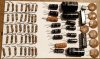
Removed most of the resistors (not all of them). I tested each resistor that I removed (41), of those, I found one resistor that had no conductivity, and one resistor that exceeded the +5% tolerance, the rest were all good. I guess I should mention that this receiver was not working when I purchased it, so finding something wrong, is a good thing. Here is another pic of the board:


Below is the 2016 Resistor Substitution Part Number list for the SX-780 Tuner Board.
 

Attachments

Last edited:
I thought carbon film resistors were OK. Carbon composition not so much. I'll have to read up later.

Do you have the means to align the tuner?
 
Sargent. Recommend (as WattHour already did) to NOT unwrap anymore Wirewrapped posts. If you must remove the lead from the board, just DeSolder the post from the board, and leave the wirewrap connection as is.

Be prepared to have an alignment done on the tuner.

One last thing. It's recommended to fix the non operable problem(s) 1st, and once you get it running (even if it sounds like shite!) you have a baseline performance.
 
I do not understand why you took the pcb out, all the parts can be changed without removal?
I do commend you in your thoroughness and documentation skills.
I do agree if you are changing certain ceramic disk caps and the like, do you have a means to check and or adjust alignment?
 
Back
Top Bottom