• The move to the new server is done. There are some software and database maintenance updates in process. This has us passing the hat around to help out. We appreciate any donations. Seriously, even a dollar helps. The payment page may be found here - https://www.audiokarma.org/support.html

SX-780 unfound question

cohwy9

New Member
There is a wealth of knowledge here that is incredible! I have searched this form for a specific problem I am having with a Pioneer SX-780 I have recently acquired, but have not quit found a similar scenario to what I am having. I will try to keep this short and concise. If you need additional info please let me know:

Problem: Right channel distortion in both headphones AND speakers A+B. I have found other posts where people are having similar issues, but just in the speakers. Also, the right power meter barely moves. When I adjust balance to max left speaker, no issues head phones or speakers. When I start to adjust balance back to the right, the distortion on the right channel comes in. When I turn up volume at max right channel with the distortion, relay pops off, but then resets.

Yes:
  • I thoroughly cleaned rca jack, switches, and all knob pots with dexoit. I did 2 separate deoxit cleanings. This includes the balance pot.
  • I removed the top and bottom, cleaned and inspected the boards. No glaring anomalies or visual capacitor issues.
  • Darlington Power Packs STK-0050 both appear to be vintage. No evidence of replacement.
  • I have also tried different speakers on both A and B.
  • I do have a voltmeter and can solder. I do not have oscilloscopes or other advanced electronic diagnostic equipment.

Question: I have found posts where people have had similar a problem, but only in the speaker output and not in the headphones. I have not found a specific post where the problem of single channel distortion in both headphone and speaker output. I am trying to at least get a starting point of where to start poking around. Do you have a link to a different post that may help me bird-dog this? Or a specific place to start looking on the inside for the culprit?

Many thank you's in advance!
 
Register to hide this ad
Thank you. I have read a number of posts about those and should be able to swap that out myself. Was not sure if my issues sounded like that was the true culprit. I read other posts and try to get one of those in house to replace.
 
I don't trust my analog multimeter to test the STK, so I ordered an new digital version. Should be here wednesday to take these STK readings.

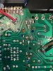
Upon closer inspection I think I do see some work on the power supply voltage regulators. Would this be any concern or potential source of my right channel issues?
 

Attachments

  • IMG_3493.jpg
    IMG_3493.jpg
    71 KB · Views: 51
  • IMG_3492a.jpg
    IMG_3492a.jpg
    87.5 KB · Views: 52
The regulator solder joints were a known issue and commonly reheated as a preventive measure.
 
Oertes - Thank you. I reflowed these solder joint. No Change to right channel distortion issues.

Next, I used my crappy old analog volt meter and got the following pin readings on the two STK's with the SX780 on, no load on speakers, mode set to FM.

Pardon me but I do not know which STK goes to which channel. The below readings are when I am looking at it upside down with faceplate/control knobs facing me.

These are as close as I could determine from using the indicator meter and having to switch +/- probs to chassis ground for negative readings:

STK-0050(on my left/behind volume control side):
Pin #1 -9.0
Pin #2 -42.0
Pin #3 -2.0
Pin #8 -2.0
Pin #9 42.0
Pin #0 -6.5

STK-0050(on my right/behind power switch side):
Pin #1 -5.2
Pin #2 -41.5
Pin #3 -1.8
Pin #8 -1.2
Pin #9 41.5
Pin #0 4.8

Am I correct that the right channel is controlled by the STK behind volume control side? This would be my problem child?
 
Finally got my digital multi-meter it. I retook the measurement on the 2 STK power packs in the Pioneer SC-780. Here are the digital readings in volts DC:

STK-0050(on my left/behind volume control side):

Pin #1 = -9.02
Pin #2 = -42.22
Pin #3 = -0.1
Pin #8 = -0.098 (yes, Negative)
Pin #9 = +42.20
Pin #0 = -6.51 (yes, Negative)

STK-0050(on my right/behind power switch side):
Pin #1 = -1.31
Pin #2 = -42.2
Pin #3 = -0.063
Pin #8 = +0.048
Pin #9 = +42.30
Pin #0 = +1.1

From my reading the proper STK-0050 pin voltages(vDC) should be (correct me if I am wrong with below):
Pin #1 = -1.4
Pin #2 = -40
Pin #3 = -0.005 (Is this correct?)
Pin #8 = +0.005(Is this correct?)
Pin #9 = +40
Pin #0 = +1.4

Based on the the above information

1) Can I conclude that the first noted STK is bad is most likely the source of my distortion on the right channel? The high negative voltage on Pin #1 and negative voltages on Pins#8 and #0 seem not so good?
2) Do you recommend checking anything else before I progress to buy a new STK-0050?
3) Would you proceed to replace both STK's at the same time? Or just only replace the one that is bad?
4) I plan on picking up one of these pre-built/tested replacement STK-0050 modules off of ebay unless you recommend a different option? Below is the link:

https://www.ebay.com/itm/STK-0050-r...rentrq:911169d31760ad4ea1be0b82ffe44dee|iid:1


As with before, I think you all for any recommendations you can provide.
 
The way you describe looking at it, the STK on your left is the right channel. The STK on your right is the left channel.
When measureing DC voltages it is better to set the input to AUX with no input signal present, and volume to minimum.
I believe you are correct:
STK-0050(on my left/behind volume control side):
Pin #1 -9.0
Pin #2 -42.0
Pin #3 -2.0
Pin #8 -2.0
Pin #9 42.0
Pin #0 -6.5
This one does have a problem, most likely the STK, but maybe more. When you get your DMM you can take better measurements.
 
STK-0050(on my left/behind volume control side):
Pin #1 = -9.02
Pin #2 = -42.22
Pin #3 = -0.1
Pin #8 = -0.098 (yes, Negative)
Pin #9 = +42.20
Pin #0 = -6.51 (yes, Negative)

There is definitely a problem in this channel. To verify it is the STK and not something else or more, and to protect a replacement, a bit more testing is in order.
You need a pair of resistors, from 220Ω to 1kΩ, value not critical, but both the same. Uninstall the STK from the defective channel and solder the resistor in its place like this:

Pioneer SX-780 red dc-test.jpg

z-adamson.jpg

Note the examples may not be the channel you are having a problem with, but it works the same, do it in place of the 'bad' one, one resistor from pin 1 to pin 3, one resistor from pin 0 to pin 8.
Power on, the relay may click. Re-measure the voltages on the pcb pins as before. Pins 1 and 0 should be close to the same voltage, but opposite in polarity, positive and negative. Balanced +/- is the important spec here, the voltages depend on the resistors value.
Post your results.
 
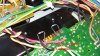
Merlynski - Thank you! STK is out. As soon as I can figure out where to buy some of these resisters I will follow your directions and repost results. The thermal bonding grease was dried out and flaky under the STK, interesting. Am assuming the other side is the same.IMG_3498.jpg
IMG_3497.jpg
 
Bad dried grease can cause the module to overheat and die. Clean all the old off, and put new under both STKs.

PS - Does it matter the Wattage of the resistor matter? Would 1 kOhm,1/2W be ok? If that would work, I am going to grab these off of Amazon. Should be here sunday:
https://www.amazon.com/Projects-100EP5121K00-Ohm-Resistors-Pack/dp/B0185FIJ9A/ref=sr_1_4?crid=2ZRV3RJ56BM22&dchild=1&keywords=1kω+resistor&qid=1608771972&sprefix=1kΩ+resis,aps,192&sr=8-4
That should be fine.

That exact same STK replacement from the 'bay is available as a PCB and heatsink plate kit also. You would then order your own parts (list of parts is provided). This is a less expensive option. I can personally vouch for that kit, as I have built it from parts myself and it works great. FWIW, IMHO the price for the assembled and tested unit is reasonable, considering the work done to assemble and test, if you do not wish to build it yourself. If you do toast one of those it is repairable.
I would do both channels the same, if you do get that one, get two.

Here is a link to that design: STK-0050 replacement for SX-780 and others | Audiokarma Home Audio Stereo Discussion Forums
 
Last edited:
Ok, I got the 1 kOhm,1/2W resistors and soldered them into Pins 1/3 and 0/8 on both STK pcb pin locations. I measure Vdc with my DMM and here are the results:

STK-0050(on my left/behind volume control side):
Pin #1 = -6.73
Pin #2 = I did not take reading
Pin #3 = -0.077
Pin #8 = -0.071
Pin #9 = I did not take reading
Pin #0 = +6.62

STK-0050(on my right/behind power switch side):
Pin #1 = -6.99
Pin #2 = I did not take reading
Pin #3 = -0.058
Pin #8 = -0.057
Pin #9 = I did not take reading
Pin #0 = +6.79

So, Pins 1 and 0 on both are close to each other with inverse polarity. Not exact reading, but close. Is this close enough? I have 2 replacement STK's on order. Should be here sometime in January.

Any other recommended measurements or action items prior to STK's coming?

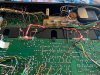
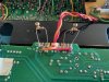
Here are a few pics of the process:

IMG_3520.jpg IMG_3521.jpg
 
Yes, about 5 seconds after I flipped the power switch on I heard the click from the relay.

I will go ahead and install the new STK's when they arrive and give an update. I do not think they will be here until latter in January, so it may be a bit.

Thank you very much for the help so far!
 
Any other recommended measurements or action items prior to STK's coming?

Test the emitter resistors for the output packs.
Do something to cool down the power supply regulators, or at the least Q25.
Consider replacing the potential troublesome transistors in a few locations - a couple of 2SA726s as switches in the FM muting area. If there is any sign of abuse at the relay driver (Q26) it can be upgraded to a KSC2690AY or equivalent.
Relamping?
Cleaning?
 
Watthour - Thank you for the suggestions. If you have any specific links to threads on the "Emitter Resistors", "Power Supply Regulators" or "Transistors" that you know of, I would appreciate you pointing me to those. Any preventative maintenance like this that you think would be good to work on prior to receiving the STK's, I will spend my time working on those.

The lamps are all working. I think I will let those ride.

As for cleaning, the outside is near mint. Inside I have done a pretty through cleaning.
 
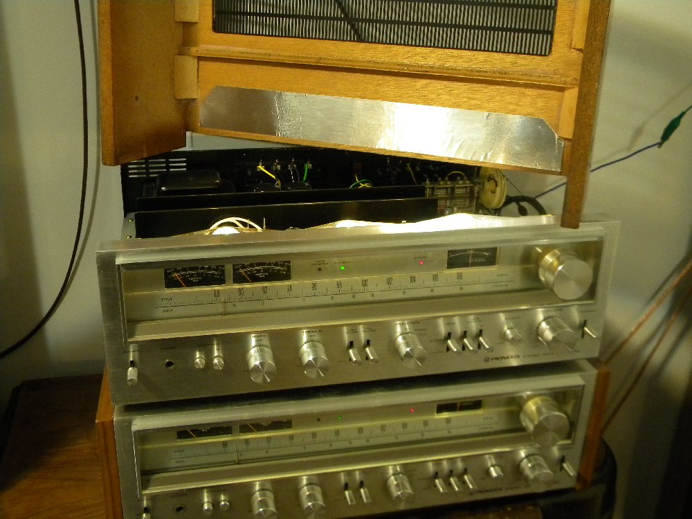
If the exterior is "mint" you might want to consider something like this to protect the veneer from scorching:

SX-780-HeatShield.jpg


Regarding the four 0.22Ω resistors, simply measure them in circuit to see if they are no more than 0.22Ω (not counting your meter's lead resistance).

For the generally hot-running Q25 regulator, this might be informative: https://www.audiokarma.org/forums/i...he-sx-780-q19-q20-and-q25-transistors.496080/
 
Last edited:
Back
Top Bottom