• The move to the new server is done. There are some software and database maintenance updates in process. This has us passing the hat around to help out. We appreciate any donations. Seriously, even a dollar helps. The payment page may be found here - https://www.audiokarma.org/support.html

SX-828 Rebuild

purple1

Well-Known Member
I have bought a complete rebuild kit from the big auction site. I have also got the LED light kit from the same seller. I have just gotten started and want to make sure I do this right. The most I have done before is simple repairs and clean switches and POTs with Deoxit, so this is going to be very involved for me.

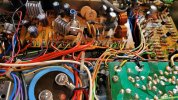
First board is the power supply. This seems to have gone very well.
 

Attachments

  • 20231117_212940.jpg
    20231117_212940.jpg
    50.5 KB · Views: 19
  • 20231117_213132.jpg
    20231117_213132.jpg
    43.6 KB · Views: 21
  • 20231117_233546.jpg
    20231117_233546.jpg
    155.6 KB · Views: 21
  • 20231118_203943.jpg
    20231118_203943.jpg
    152.6 KB · Views: 21
  • 20231118_204234.jpg
    20231118_204234.jpg
    45.1 KB · Views: 21
Register to hide this ad
Next is the protection board. I have just gotten started with this one.

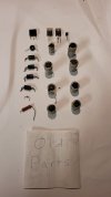
Last pic is the whole kit and the new LED lights.
 

Attachments

  • 20231119_195331.jpg
    20231119_195331.jpg
    49.4 KB · Views: 16
  • 20231119_193001.jpg
    20231119_193001.jpg
    118.7 KB · Views: 16
  • 20231119_181150.jpg
    20231119_181150.jpg
    140.3 KB · Views: 15
  • 20231119_181141.jpg
    20231119_181141.jpg
    41.5 KB · Views: 15
  • 20231117_212629.jpg
    20231117_212629.jpg
    101.8 KB · Views: 14
I just finished one. the double sided tone board is FUN! I had an old cold solder joint on it that would cause the left channel to drop out. so check that out and reflow the solder if needed.
 
make sure you TEST the receiver after every board you do. if you screw up during the rebuild without checking you will paint yourself into a corner that will be hell to get out of. there are no COLD solder joints, just overheated ones
 
You've got the later AWM-025 protection board as used in the 737 - 939 - 1010. Add a 1n4004 to pins 9 and 10 (cathode side to Pin 10). This will prevent backfeed to Q7 (2sc1384) and eventual breakdown of Q7 when the relay field collapses on shut down . This was added by pioneer in later models.

You still got that FISHER Console?????
 
I see that I have AWM-025 B. It was confusing me when things did not match the service manual or the instructions. I replaced the caps. And then replaced a 399 W with the C2383 that came in the kit. Looked like a similar part.

That's where I am now. I'm just wondering if I should replace much more here? Every thing is working at this point. What other parts on this board do you think need replaced?

Larry, I do still have the Fisher.
 
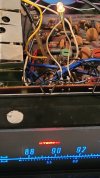
I went ahead and started the LED replacement kit. Got all but the 4 speaker lights replaced. Now the stereo light (new LED) stays on all the time. Did I eff something up?
 
No FUBAR on your part, but put the incandescent back in on the Stereo light. LED's can and do run at a wider range of voltages than an incandescent does. The Stereo indicator circuit is more a differential voltage circuit than a straight hot neutral. Power supply on one side and tuner chip on the other. When there is no signal for the multiplexer, the voltages on either side of the lamp stay almost equal. When a MPX signal is captured, the chip side literally grounds and the light comes on. IIRC there's about a 2v difference between sides when light is off which can set off the LED, while the incandescent stays dark.
 
No FUBAR on your part, but put the incandescent back in on the Stereo light. LED's can and do run at a wider range of voltages than an incandescent does. The Stereo indicator circuit is more a differential voltage circuit than a straight hot neutral. Power supply on one side and tuner chip on the other. When there is no signal for the multiplexer, the voltages on either side of the lamp stay almost equal. When a MPX signal is captured, the chip side literally grounds and the light comes on. IIRC there's about a 2v difference between sides when light is off which can set off the LED, while the incandescent stays dark.
Thanks Larry. I'll give it a try and let you know. I wonder if putting a couple of diodes in series would drop those couple of volts and let the LED work properly?

I sure would like to keep the LED, but it needs to work. Any other ideas to get the LED working?
 
How about that? I put the incandescent back in the circuit and now everything seems to work. The LED is still in there. I just added the bulb.
So it looks like this 828 needs the bulb just to work.
 

Attachments

  • 20231124_114407.jpg
    20231124_114407.jpg
    97.1 KB · Views: 9
The differential voltage is really small, probably less than .5v, but the LED doesn't present a load on the circuit to pull down the voltage to a null. So it stays lit. The incandescent will draw .5a or 50ma which in this case is sufficient to get a null voltage and shut down the LED.
 
I think maybe the tuner is at fault here. Now that I put the bulb back in the light is on again. It gets brighter when FM stereo is tuned and it's on FM.
Hopefully when I install the tuner section of the kit, it will fix this. I will revisit this when I get to the tuner section.
 
Back
Top Bottom