• Please note that Audiokarma will be offline briefly for updates early on Monday morning, September 28th.

SX-850 failing DBT and no relay click after work on Power Amp

Gobstopper

Active Member
Hello Everyone, continuing work on the SX-850. I rebuilt the power supply and updated caps and transistors on Protection circuit and EQ board, was working fine after that. I then swapped out the electrolytics and transistors (other than the output transistors attached to heatsink) on the power amp. I tested it plugged into the DBT and the bulb stays very brightly lit with no relay click. I started trying to check voltages and found the power supply outputs were very low, but I don't know if that's because it's going through the DBT. I looked at the back side of the power amp board, and nothing obvious popped out at me. Reflowed a few of the connections that looked a little questionable, but still nothing.
I tried looking around, but I couldn't find the general method for trouble shooting a short.

Any suggestions on how to get started?
 
Register to hide this ad
The above. Assuming you replaced the trimmers, as I really hope you did, make sure they are adjusted for zero bias current.
 
I was looking through my BOM, and for Q5-Q8 I had the following:
Q5,Q6 2sa818 ->ksa1220AYS
Q7,Q8 2sc1628->ksc2690AYS

Problem is I can't find the source material for those replacements, and everything I've seen since uses a different substitution for each pair. Does having 1220s and 2690s in there provide an explanation for the short? I think the npn vs pnp aspects are correct, but beyond that....I replaced trim pots at same time I replaced caps and transistors. Bias current was set to zero (rotated fully counter clockwise per the SM)

I have checked orientations of components several times, but will check again tomorrow.
 
I was looking through my BOM, and for Q5-Q8 I had the following:
Q5,Q6 2sa818 ->ksa1220AYS
Q7,Q8 2sc1628->ksc2690AYS

Problem is I can't find the source material for those replacements, and everything I've seen since uses a different substitution for each pair. Does having 1220s and 2690s in there provide an explanation for the short? I think the npn vs pnp aspects are correct, but beyond that....I replaced trim pots at same time I replaced caps and transistors. Bias current was set to zero (rotated fully counter clockwise per the SM)

I have checked orientations of components several times, but will check again tomorrow.
The correct pair is KSC3503 and KSA1381, although I'm sure the ones you have in there are fine for now as long as they are the correct orientation. Make sure you have those trimmers the right way, adjust them to the middle on DBT just for kicks. I'm hoping it's something simple like that.
 
Last edited:
The trimmers COULD be causing this, ESPECIALLY if the 10k and 100 ohm pots are interchanged. Check that first, it's easy with how this board is laid out.
The 100 ohm pots are used as variable resistors, sharing one end and the center tap on the SAME foil.
The 10k ohm pots have THREE distinctly separate foils to connect to.

After they are correct:
The 10k pots should be set halfway.

The 100 ohm pots should be set to ZERO ohms. MEASURE it. None of this CCW or CW bupkus.
IF they were set to 100 ohms, the commanded idle current would be horrendous, as Pioneer uses 18 mA in that circuit
so 100 ohms would yield 1.8 volts, too much by far added to the +/- 1.2v (2.4v tot) from .the STV-4h

652-3386H-1-101LF 100ohms 3386H Single Turn 3/8" ? 10% parallel to pcb, triangle of pins ccw min#1 triangle lead pattern
sx-850 idle current


652-3296P-1-103LF 10Kohms 3296P Multi Turn : 12 3/8" Sealed parallel to pcb
sx-850 offset voltage adjust- parallel to board
 
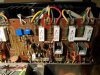
I didn't get home in time to remove the trimmers from the board to measure resistances, but I did manage to take some pics. In the process of looking over the pictures I noticed that the wire to pin 38 of the power amp (Base of one of the 2s427s) had snapped, probably while moving heat sink back and forth. I had removed the STV-4H from the heatsink, thank goodness one of those didn't snap off at the body. Even if that doesn't explain the short (which it should, right?) I'm left with finding the best way to reattach the wire. I do have a wire wrap gun with a bit for 22 gauge wire, but I'm not sure what gauge wire is used, the insulation at least looks a lot thicker than elsewhere in the unit. Recommendations on how to proceed? Also, for future reference, do most people just lift the heat sink over , or remove connections to the output transistors?power_amp.jpg
 
The easiest way to service the power amp pcb is to first carefully remove the TO-3 devices attached the heatsink, so that the wires/sockets are free to move without restraint. make sure you mark, I just write in pencil on top of the HS, where you removed and replace in the same positions.
You can solder that wire back, it does not need to be wrapped back on the post. The post and wire are oxidized, you should clean off the oxide, fine file/sand paper to be able to get the solder to flow. You only need min. one wrap around the post then solder. Check continuity after soldering.
 
Last edited:
On the four I've done, I just put the unit on it's side and flip out the heatsink so the amp board is accessible. Quick, no fuss, minimal strain on wires.
 
Thanks for the tips, I think I will try to keep wires attached, lay on side, and flip out heatsink.

One last question(for now). While KSC3503DSTU is in stock, Mouser doesn't expect to receive any KSA1381ES until November!!!!

Is there another source for KSA1381ES I can order from, or other another equivalent 1381/3503 pair that would work?(I only need 2 of each)
The other options would be
1)keep the 1220AYS and 2690AYS combo that I put in ( I still don't know where I came up with that substitution)
2) put the original transistors back in.

I was going to get some UF4004s that I missed on the original parts list, along with the recommended 1381/3503 combo and the puts those parts in before reconnecting the snapped wire, but now not sure on best course of action.
 
Thanks KVflyer. I did see some on "the auction site", but there is always the risk of fakes (especially from the sellers in China apparently) and the other issue is the exorbitant cost even for US or UK sellers. Maybe originals are the best bet, unless someone can verify that the 1220/2690 combo is OK until November at least.
 
I'm not keen to get transistors from China either, or off the auction site at all for that matter!
Update: I reconnected the snapped output transistor wire, and tested on DBT again, no dice, still a short somewhere. My reasoning was if I blew a transistor somewhere, I'd rather find out before placing an order for the missing rectifiers and a few other parts. Bummed, I was really hoping that was the problem. Now to remove components and start checking for shorts and resistances.

No thoughts on whether the 1220/2690 pair would work in place of 1381/3503?
 
I'm not keen to get transistors from China either, or off the auction site at all for that matter!
Update: I reconnected the snapped output transistor wire, and tested on DBT again, no dice, still a short somewhere. My reasoning was if I blew a transistor somewhere, I'd rather find out before placing an order for the missing rectifiers and a few other parts. Bummed, I was really hoping that was the problem. Now to remove components and start checking for shorts and resistances.

No thoughts on whether the 1220/2690 pair would work in place of 1381/3503?
Like I said in post #6, that transistor pair should be fine for the time being. Certainly won't cause a DBT short unless they're installed wrong.
 
Thanks Ivan, Just wanted to confirm since I wasn't sure if "for the time being" meant just for now (very short term), or until I was able to get the necessary parts. Didn't want to get too comfortable (assuming I get the short fixed), crank up the unit at some point and blow something out because Transistors weren't up to snuff.
 
Found the short problem, the KSA940s and the KSC2703TUs were switched in my BOM, so wrong BJT in the wrong spots. Sigh... Anyhow, I was testing the transistors before putting back in, and one of the 2073s has .86V diode check voltage (positive on Base) and the other shows .58V (positive on Base). Both show 0 L (or infinite) if I switch the leads of the DMM around. Are they both okay or is the .86V one shot? All my other transistors have always tested in the ~.58 V range. I should perhaps point out that both are mounted on their own heat sink, but not in circuit.
 
Back
Top Bottom