• The move to the new server is done. There are some software and database maintenance updates in process. This has us passing the hat around to help out. We appreciate any donations. Seriously, even a dollar helps. The payment page may be found here - https://www.audiokarma.org/support.html

SX-850 Speaker relay keeps tripping

worthiersky8

New Member
I have few old receiver I have collected over the years, basically we have always used them for our sound systems, as one would be going out I would some how get another one. But as good old equipment is get hard to find (and I finally have a work bench again) I am going through these old receivers and trying to get them working again.
So I have an old SX-850. When you first turn it on you hear the relay click on after about 2 or 3 seconds, music comes out the speakers just fine but as you are listening it the relay will intermittently click off and almost immediately click back on. Sometime it will do it a few times in succession and not do it again for a few minutes. I thought it was the relay going bad so I replaced it a new one and It did improve it a slight bit but still didn't completely fix the issue. Any advice any one can give me will be greatly appreciated as this is my favorite receiver and really want this one working.
 
Register to hide this ad
Check idle current and DC offset as explained in the SX-850 service manual. Once done with that post voltage readings from the power supply and protection board.
 
DO NOT even breath on the bias trim pots unless you have the unit hooked up on a dim bulb tester (do a search here). Check the power supply board for cracked solder joints. Replace the 2SC869 (Q1, Q2) transistors on the protection board with KSC2383.
 
So I am getting some pretty off numbers on the power board
pin #6,7 8.7v
pin #8,9,10 5.2v
pin #11 2.7v
pin #15 52.7v
pin #22,23,29 0

L speaker -7mV
R speaker -27mV
 
Relay drive transistor. Change AWM-062 board Q7 2sc1384 to a new ksc2690 (512-KSC2690AYS)

lots of other stuff to do, for reliability, but q7 is the likely suspect from your description.
 
Can your please report the voltages on some of the other pins on the AWR-101 board? Bear in mind that several of the circuits will have AC voltage.
 
Sorry it was really late last night when i posted that

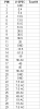
arw-101

pin vspec = test
1 gnd = 0
2 5.4 = 5.35
3 5.4 = 5.35
4 13.5 = 13.6
5 13.5 = 13.6
6 51.5 = 8.7
7 51.5 = 8.7
8 36.5 = 5.2
9 36.5 = 5.2
10 36.5 = 5.2
11 28 = 2.7
12 gnd = 0
13 -13.5 = -13.5
14 -51.5 = -52.7
15 -19 = -52.7
16 36AC = 33.9AC
17 -45 = -47.1
18 45 = 47.2
19 36AC= 33.9AC
20 gnd = 0
21 gnd = 0
22 7.5AC = 6.6AC
23 7.5AC =6.6AC
24 7.5AC = 7.0AC
25 49AC = 48.7AC
26 49AC = 48.7AC
27 19AC = 20.4AC
28 19AC = 20.4AC
29 7.5AC= 6.6AC

arrggg it keeps deleting my spaces
 
Last edited:
in case it helps
awm-062

pin test vspec
1 7.7
2 -13.5 = -13.5
3 7.7
4 0 = gnd
5 7.8
6 7.8
7 7.8
8 7.8
9 2.69
10 5.3 = 36.5
11 5.3
12 6.6AC =7.5 AC
 
Last edited:
All the transistors, the electrolytic caps, and switch the C1 and C2 to film caps.

Protection Board (AWM-062)

AWM-062: C1: .22uF 10v CSSA: 505-MKS2C032201BKI00 .22uF 63v
AWM-062: C2: .22uF 10v CSSA: 505-MKS2C032201BKI00 .22uF 63v
AWM-062: C3: 330uF 6.8v CEA: 647-UPW1A331MPD 330uF 10v
AWM-062: C4: 330uF 6.8v CEA: 647-UPW1A331MPD 330uF 10v
AWM-062: C5: 4.7uF 25v CEA: 647-UPW1V4R7MDD 4.7uF 35v
AWM-062: C6: 100uF 16v CEA: 647-UPW1V101MPD 100uF 35v
AWM-062:Q1: 2SC869: 2SC945A 512-KSC1845FTA
AWM-062:Q2: 2SC869: 2SC945A 512-KSC1845FTA
AWM-062:Q3: 2SC869: 2SC945A 512-KSC1845FTA
AWM-062:Q4: 2SC869: 2SC945A 512-KSC1845FTA
AWM-062:Q5: 2SA733: 512-KSA992FBU
AWM-062: Q6: 2SC945: 512-KSC2383YTA
AWM-062:Q7: 2SC1384: 512-KSC2690AYS
 
Back
Top Bottom