


DAY4201
Active Member
I hope this will be a clear representation of how to adjust the tuner dial indicator so that it covers the entire frequency scale. The adjustment described here may or may not be necessary if the tuning drum has been removed and then replaced. Also, this is not about how to adjust or “align” the tuner.
It comes from my experience and frustration with trying to adjust the indicator after I recapped the “tuner assembly” (AWE-071) on my SX-850 which required removing and replacing the tuning drum.
The SM for the SX-850 covers how to replace the dial cord (pg. 33) but I have not found an explanation of how to adjust the “tuning drum assembly” or more specifically the “tuning gang gear”. There are no SM part numbers that I have found for the part I am focusing on, so I am using my own terminology which I apologize for in advance if it is somehow misleading.
While I assume this adjustment will work for other Pioneer’s from the SX series especially the SX-950 and maybe others.
To begin this adjustment it is essential that the tuner gang is located at the lowest point it will turn at the low end of the frequency scale. While it is possible to do this adjust with the gang adjusted to the highest part of the scale, I found it easiest to start with the gang at the lowest end of the scale.
The first photo shows the “tuning drum” mounted on the assembly just for reference.

The second photo shows the “tuning drum assembly” (AXA-113) with the drum removed. How to remove the drum and maintain the dial string in place is discussed by others but I will just say I used “painter’s tape” to hold the string in place and taped the drum to the side of the chassis while recapping the tuner board. IMO painter’s tape holds well and is much easier to remove than something like duct tape.

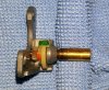
The “tuner gear housing’ (my term) is held on with 2 screws and fits over the nylon gear on which the tuning gang is mounted. It is easy to remove and does not come apart. This part is made up of 3 parts which are not removable. They are the drum mounting shaft, a small nylon gear and what I would call a nylon stop ring. Photo 3 show this part once removed. I have added green highlighter to the gear and orange to the stop ring to aide in this discussion.
In Photo 4 the gear housing has been removed. The gang shaft gear is completely exposed. Again, the gang has been adjusted to the lowest part of the frequency scale. I have added an orange line and a green line opposite it. It appears that the split in the gang shaft is parallel to the chassis in this position. That may be a coincidence, but it is the same on both my unit and the additional tuner assembly I purchased to for several replacement parts I needed.
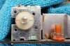
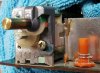
Photo 5 shows the proper position of the green colored gear and the orange stop. It is essential that they are in this position and stay in this position when the gear housing is replaced. They will want to move some. If they are not tight in the upper position (as seen in the photo) the gang will not traverse the full scale. It will be short on the high end. I learned this after a number of trials.

Once mounted properly. The tuning drum can be remounted. To get it remounted it maybe necessary to give the dial cord some slack by pulling the spring on the drum forward. Once mounted the cord should be taunt but not overly so IMO. If it was OK before it should be fine once the drum is back on and secure. I try to remount the drum in the same position it was in prior to removing it and tighten the screw that holds it in place.
Now to test. The SM describes how to move dial pointer to the proper location. That needs to be done as described. Once that is done, turn the tuning dial up the frequency scale. It should stop in the proper position at the end of the scale. Photo 6 shows the position of the orange gear and green stop in that position. They are now in the back of the gear housing and the gang is in what I call the “up” position or at the highest point on the frequency scale.
I hope this explanation is useful and sorry if it is too long or somehow incorrect. It is based on my experience and that is it. I am clearly not an expert related to tuners or anything else electronic. It is my effort to contribute to the cause and again say thanks for all the help I have received on AK.
Please let me know if I have missed something or if I should add anything.
It comes from my experience and frustration with trying to adjust the indicator after I recapped the “tuner assembly” (AWE-071) on my SX-850 which required removing and replacing the tuning drum.
The SM for the SX-850 covers how to replace the dial cord (pg. 33) but I have not found an explanation of how to adjust the “tuning drum assembly” or more specifically the “tuning gang gear”. There are no SM part numbers that I have found for the part I am focusing on, so I am using my own terminology which I apologize for in advance if it is somehow misleading.
While I assume this adjustment will work for other Pioneer’s from the SX series especially the SX-950 and maybe others.
To begin this adjustment it is essential that the tuner gang is located at the lowest point it will turn at the low end of the frequency scale. While it is possible to do this adjust with the gang adjusted to the highest part of the scale, I found it easiest to start with the gang at the lowest end of the scale.
The first photo shows the “tuning drum” mounted on the assembly just for reference.
The second photo shows the “tuning drum assembly” (AXA-113) with the drum removed. How to remove the drum and maintain the dial string in place is discussed by others but I will just say I used “painter’s tape” to hold the string in place and taped the drum to the side of the chassis while recapping the tuner board. IMO painter’s tape holds well and is much easier to remove than something like duct tape.
The “tuner gear housing’ (my term) is held on with 2 screws and fits over the nylon gear on which the tuning gang is mounted. It is easy to remove and does not come apart. This part is made up of 3 parts which are not removable. They are the drum mounting shaft, a small nylon gear and what I would call a nylon stop ring. Photo 3 show this part once removed. I have added green highlighter to the gear and orange to the stop ring to aide in this discussion.
In Photo 4 the gear housing has been removed. The gang shaft gear is completely exposed. Again, the gang has been adjusted to the lowest part of the frequency scale. I have added an orange line and a green line opposite it. It appears that the split in the gang shaft is parallel to the chassis in this position. That may be a coincidence, but it is the same on both my unit and the additional tuner assembly I purchased to for several replacement parts I needed.
Photo 5 shows the proper position of the green colored gear and the orange stop. It is essential that they are in this position and stay in this position when the gear housing is replaced. They will want to move some. If they are not tight in the upper position (as seen in the photo) the gang will not traverse the full scale. It will be short on the high end. I learned this after a number of trials.
Once mounted properly. The tuning drum can be remounted. To get it remounted it maybe necessary to give the dial cord some slack by pulling the spring on the drum forward. Once mounted the cord should be taunt but not overly so IMO. If it was OK before it should be fine once the drum is back on and secure. I try to remount the drum in the same position it was in prior to removing it and tighten the screw that holds it in place.
Now to test. The SM describes how to move dial pointer to the proper location. That needs to be done as described. Once that is done, turn the tuning dial up the frequency scale. It should stop in the proper position at the end of the scale. Photo 6 shows the position of the orange gear and green stop in that position. They are now in the back of the gear housing and the gang is in what I call the “up” position or at the highest point on the frequency scale.
I hope this explanation is useful and sorry if it is too long or somehow incorrect. It is based on my experience and that is it. I am clearly not an expert related to tuners or anything else electronic. It is my effort to contribute to the cause and again say thanks for all the help I have received on AK.
Please let me know if I have missed something or if I should add anything.
Last edited:
