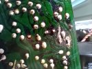
This is my first restoration have read a ton of threads. Thanks everyone for your inputs its helped. I am going to clean up my heat sinks also and re compound them. I have a question concerning cap replacement on the Power Supply. Which 2 caps get replaced with Wima's 4.7 uf 63?. Does it matter>


You are using an out of date browser. It may not display this or other websites correctly.
You should upgrade or use an alternative browser.
You should upgrade or use an alternative browser.
SX-980 Restoration #1
- Thread starter Dan'o
- Start date
Register to hide this ad

First, welcome to AK.
Next, yes it matters what value you use to replace existing parts. There are only two 4.7µf caps in the power supply and they are C19 & C20.
Are you using a service manual? There is one right here in the AK database:
https://akdatabase.com/AKview/albums/userpics/10007/Pioneer SX-980 Service Manual.pdf
I'm also wondering about where you got the parts you're asking about.


Next, yes it matters what value you use to replace existing parts. There are only two 4.7µf caps in the power supply and they are C19 & C20.
Are you using a service manual? There is one right here in the AK database:
https://akdatabase.com/AKview/albums/userpics/10007/Pioneer SX-980 Service Manual.pdf
I'm also wondering about where you got the parts you're asking about.
Last edited:
Hey kwade. Thank you for the response. I kinda thought it would be those 2, but wanted to be sure.
I bought the kit from Marblehead Audio. They have given me very good instructions and hints to do this restoration.
And yes I have a copy of the service manual and parts list.
I bought the kit from Marblehead Audio. They have given me very good instructions and hints to do this restoration.
And yes I have a copy of the service manual and parts list.
One needs to be careful when getting those kits. Marblehead has kits with wrong parts and hifiaudio is just plain terrible.Hey kwade. Thank you for the response. I kinda thought it would be those 2, but wanted to be sure.
I bought the kit from Marblehead Audio. They have given me very good instructions and hints to do this restoration.
And yes I have a copy of the service manual and parts list.
Hope the rest of your work goes well.
Oh Man! That's all I need right now. But will check everything twice to be right!One needs to be careful when getting those kits. Marblehead has kits with wrong parts and hifiaudio is just plain terrible.
Hope the rest of your work goes well.


That's the problem, even if it's the right value doesn't mean it's the right part....Oh Man! That's all I need right now. But will check everything twice to be right!
I hate those kits with a passion.
The two Wima caps don't belong in the power supply. I looked at the caps they sold and said they used Nichicon UPW and UKL primarily. Look for two Nichicon UPW caps of that value to put there. 4.7µf 50v.
The Wima's belong in the signal path, not in the power supply.
The Wima's belong in the signal path, not in the power supply.
Idiots. I finished putting together an amp for a guy who used a Marblehead kit a few years back. Wrong parts, parts that didn't fit where they were supposed to.Some of their kits use Wima for everything at 4.7 uf or lower.
I asked them if they ever put one in an amp and they said no. They just look up service manuals and choose parts that they think should work, throw them together and call it a restoration kit.
Can't fit a part twice the size of the original in a tight spot. Can't adjust trim pots that have the adjusting screw on the wrong side. Can't install filter caps that have leads spaced wrong.
Idiots.
Ok, cleaned the heat sinks, re-compound them. Replaced all the caps.. Noticed somebody was doing some work prior to me. I saw where Q4 is and there was a bad trace and solder. Repaired and checked continuity all is good to pin 27.
Turned on unit waited 6 secs no click. Have power to the lights but no function lights working.
Power Supply volts:
Pin 1-19.7
2-19.7
3-6.3
4-Gnd
5-39.9
6-39.9
7-7.6
8-
9-54.2
10-54.3
11-54.3
12-20.7
13-20.7
Protection Circuit:
Pin 1-20.6
2-66.8
3-Gnd
4-2.8
5- -1.2
6
7
8-1.3
9-3.3
10-71.0
What did I do wrong? I cleaned the posts on the power amps and deoxIT to the connectors. Saw a thread about that, but didn't help.
Turned on unit waited 6 secs no click. Have power to the lights but no function lights working.
Power Supply volts:
Pin 1-19.7
2-19.7
3-6.3
4-Gnd
5-39.9
6-39.9
7-7.6
8-
9-54.2
10-54.3
11-54.3
12-20.7
13-20.7
Protection Circuit:
Pin 1-20.6
2-66.8
3-Gnd
4-2.8
5- -1.2
6
7
8-1.3
9-3.3
10-71.0
What did I do wrong? I cleaned the posts on the power amps and deoxIT to the connectors. Saw a thread about that, but didn't help.

Fuses all still good? Don’t have a dim bulb tester? It’s best to start the unit up on the DBT after each work session. Even a seasoned tech can short a trace or install a component incorrectly. The DBT will save your butt in these situations. It’s likely that you may need to readjust the amplifier boards following a power supply rebuild. You may want to unplug those hard to find output transistors from the amp boards while you sort things out.
It looks like the dial lamps run on AC, but the indicator lamps run on a regulated DC voltage. Pin 18 on the power supply. Maybe a cap installed backwards? Did you change any transistors or diodes in the power supply?
I’ve worked three 980’s and noticed some differences in the power supplies and amplifier boards. Pioneer made revisions to the 980 so I’m not sure how a recap kit would work out here.
It looks like the dial lamps run on AC, but the indicator lamps run on a regulated DC voltage. Pin 18 on the power supply. Maybe a cap installed backwards? Did you change any transistors or diodes in the power supply?
I’ve worked three 980’s and noticed some differences in the power supplies and amplifier boards. Pioneer made revisions to the 980 so I’m not sure how a recap kit would work out here.
Last edited:
Please check fu5 and fu6 fuses on the power supply. That 7.5 dc voltage needed to run the indicator lamps is pulled down via r18 120 ohm resistor from a 13v dc supply. That 13v supply is needed for the protection circuit IC chip! pin 9 on the protection circuit. Please measure the DC voltage at pin 16, 17, and 18 on the power supply.
Blown FU5 or FU6? C13 or C23 installed backwards?

Blown FU5 or FU6? C13 or C23 installed backwards?
Last edited:
So, fuses are good and caps are installed correctly. Got it!
Can you measure the other power supply voltages? Let’s see how the rest of the power supply is doing.
Pins:
20
22
23
25
27
28
Need to check Q5 and Q6 on the power supply. Are you familiar with testing transistors? If not you can look up the 6-way test on the forum. You should be able to check them in circuit. You can also measure the voltage at the base of Q5 and base of Q6. Please be careful if you decide to do this. Dont short anything!
What other boards have you worked on outside of the power supply? That 13v feeds a few other boards throughout the unit (Protection, tuner, power meters). Something on another board could be pulling the voltage down.
Can you measure the other power supply voltages? Let’s see how the rest of the power supply is doing.
Pins:
20
22
23
25
27
28
Need to check Q5 and Q6 on the power supply. Are you familiar with testing transistors? If not you can look up the 6-way test on the forum. You should be able to check them in circuit. You can also measure the voltage at the base of Q5 and base of Q6. Please be careful if you decide to do this. Dont short anything!
What other boards have you worked on outside of the power supply? That 13v feeds a few other boards throughout the unit (Protection, tuner, power meters). Something on another board could be pulling the voltage down.
Last edited:
Pin-20 12.0
21-gnd
22-16.5
23-6.3
25-25
27- -66.7
28-0
Okay. Looks like most of the power supply is not working. Can you elaborate about the Q4 trace repair you mentioned above? Any chance of a picture of that area? Make sure that you didn’t break a wire off from a wire wrap post on the power supply. That’s easy to have happen without realizing it.
Please review that the capacitors are installed correctly throughout the entire power supply. Here is a picture of the unit that I reworked recently. Maybe you can use this picture to check your caps are installed correctly.