goatropercu
Goon
Hello,
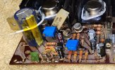
I have an SX1500TD with a short and could use some help. The amp arrived with blown fuses and blown finals on the left channel. Right channel had mismatched output transistors and the entire amp board had been removed. The previous handy work to reconnect the board was atrocious and I assume why the amp blew again.
I have replaced all of the outputs with MJ21194G, replaced the caps on the amp board, as well as the 2x C458's (C1845's as replacements). Powering up on dbt there is still a short. I took some voltage readings at the power supply and although very low seem to be within the expected trend of what is called out in the SM. When I remove both B+ fuses from the power amp board the dbt goes dim, dial lamps brighten up, and ps voltages come up to spec so I assume the problem is within this board. With just one amp board fuse installed the DBT remains bright, it doesn't matter if the one is the left or the right channel.
First thought was that I have installed something backwards on both channels, but I have double checked my work and as far as I can tell that is not the case.
I will post some amp board voltages, but based on a quick run through with the meter it looks like both channels are behaving the same.
Thank you.
Last edited: