• The move to the new server is done. There are some software and database maintenance updates in process. This has us passing the hat around to help out. We appreciate any donations. Seriously, even a dollar helps. The payment page may be found here - https://www.audiokarma.org/support.html

TA7343AP based FM Stereo Decoder for a Beomaster 1000

HatoftheCat

New Member
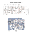
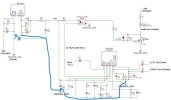
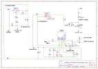
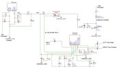
I'm trying to replace the original MPX decoder board in my 1964 vintage B&O Beomaster 1000 which is pretty noisy with one based on a TA7343AP chip. The original board connects in via an old style tube socket noval connector that provides -30v DC rail and Chassis GND. Other pins provide the MPX signal, the L & R output audio and connection to the stereo indicator lamp. The lamp is an incandescent bulb attached via a resistor to the -30v rail and on the original board is switched on by an AC128 transistor that provides route to ground when switched on. I do not intend to replace the incandescent with an LED and want to retain the simple noval plug connection so my new board will be a straight swap that I can apply to receivers of this same model (many of them never had stereo decoder board fitted as it was a paid for optional extra). To provide the power supply for the TA7343AP circuitry I am using a RECOM RS-2409S to provide me with a +9v supply relative to the chassis ground. Currently can see the voltage at pin 6 the TA7343AP drop down to 0.7v as expected when tuned to a known good stereo station but scoping the L/R outputs shows same audio signal on each so still mono. How do I check for 19/38kHz signals on this chip ? Has anyone experience of using this chip and getting it working in vintage equipment ? My design uses the pin 6 connected to LED side of a PC817 optocoupler the other side of which drives the gate of an IRLZ44N switching the indicator lamp on/off, schematic attached.
 

Attachments

  • Schematic_Beomaster-1000-FM-Stereo-Decoder_2026-01-21.jpg
    Schematic_Beomaster-1000-FM-Stereo-Decoder_2026-01-21.jpg
    48 KB · Views: 16
Register to hide this ad
Thanks but I'd already gone through the datasheet, it was bugger all help as to what I should actually be seeing on pin 6 as regards the pilot signal. However investigating the problem I've realised the power supply from the RECOM RS-2409S is absolute pants and noisy as heck despite the datasheet advised filtering of input and output . Soooooo.... much noise :( that whilst I could actually make out a square wave 38kHz signal at pin 6 on my scope it was completely drowned in much larger (switching noise ?) from the supply. So I am going to try a linear voltage regulator after the DC-DC converter to clean things up, I've ordered a LM2940T in 8v version so will see how that goes.
 
Do you know what the factory used to reduce the 30 volt supply? Datasheet for the TA7343 says Vcc 3.5-12 volt. DC to DC converter could introduce noise, that would make the decoder not work as designed? Straight voltage regulator is the way to go. Good luck.
 
The rail is -30v so a voltage regulator alone is just not going to able to give me +8v above chassis ground, that has been the crux of the problem :rolleyes: Thus why a DC-DC converter was needed that could handle that value of negative voltage AND allow me to reference the output to the chassis ground, I did try just a voltage regulator initially but the dim bulb tester glowed wonderfully bright revealing my error in not spotting it was a negative supply rail :confused: The original B&O decoder board from 1964 did not actually reduce the -30v at all, they just built the board from discrete components based on that being the supply, we are actually talking about germanium transistors here, probing that board for pilot and 38kHz is a breeze with 6 different marked test points. However obviously no one ever designed an MPX decoding IC with that -30v supply in mind, so I just have to clean up my +8v by adding the voltage regulator after the DC-DC converter... the parts list for this "quickie" project is getting longer every time I look at it :rolleyes: Will post how it goes when I have the LM2940T in hand. Fingers crossed eh !
 
Last edited:
I would get it working properly with a normal 12V supply first, and then add the -30 supply.
Don't fully get the resistance to just adding a supply wire from the + power supply, but I guess you are trying to sell upgrade boards to others. It's a lot of hand stands to just use the old wiring plug.
 
I would get it working properly with a normal 12V supply first, and then add the -30 supply.
Don't fully get the resistance to just adding a supply wire from the + power supply, but I guess you are trying to sell upgrade boards to others. It's a lot of hand stands to just use the old wiring plug.
There's literally a plug connection point right right next to where the decoder board fits in, so not interested in a bodge wire solution. A literally "plug & play" solution but not actually looking to sell any boards but possibly add into any others of this receiver I restore, its more than just for challenge if anything. Working directly with the -30v is also useful right now as that is what the stereo indicator bulb which is buried elsewhere in the tuning panel of the receiver is working with and I need to drive the switching of that as part of the design as it has to come from the TA7343AP pin 6
 
Data sheet says measure 38K signal free running on pin 6 - that means no input (so it isn't synching to a carrier signal), and they put a 330K resistor from pin 6 to ground before measuring.
 
Sorry, some how missed understanding the only source of power was that negative -30 volt line available from the socket. So how about getting the decoder board working with an external power supply first, then maybe there is better DC to DC converter that is design differently that might work? At worse the decoder project would need an additional adapter. Yes those negative build circuits are a pain. You would think that there would be a negative circuit built mpx decoder IC?
 
Hope this help others to help you.
 

Attachments

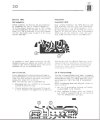
  • Beo master 1000 8.jpeg
    Beo master 1000 8.jpeg
    159.2 KB · Views: 14
  • Beo master 1000 3.jpeg.png
    Beo master 1000 3.jpeg.png
    564.3 KB · Views: 13
  • Beo master 1000 7.jpeg
    Beo master 1000 7.jpeg
    113.4 KB · Views: 12
If you have the room, try a transformer plus linear regulator. No need to run from the existing supplies. The transformer can come from a wall wart of the appropriate voltage to drive a diode bridge plus a linear regulator.
 
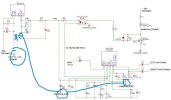
I wonder if your DC to DC converter negative should just be connected only to circuit grounds of the decoder? See diagram below to know what I mean.
 

Attachments

  • Schematic_Beomaster-1000-FM-Stereo-Decoder_2026-01-21b.jpg
    Schematic_Beomaster-1000-FM-Stereo-Decoder_2026-01-21b.jpg
    54.5 KB · Views: 6
Last edited:
There's literally a plug connection point right right next to where the decoder board fits in, so not interested in a bodge wire solution.
I'd rewire the plug then with + voltage at the other end. These chips run better at 12V than 8V, many times you can see this in the chip performance curves.
I understand the challenge of the elegant solution, but it may be the worse sounding solution, especially since you really can't fully eliminate the DC-DC noise generator so close by. The front panel stereo light is easy to do, if you can re-wire what is going to that. But then again, I get this is a Bang'er, and may be not so easy to get into certain areas because looks preceded serviceability in the design.
If you really want to use the DC-DC and reduce noise, you likely need to add a good noise filter with multiple inductors and capacitors to the line at the output. Here's a little kit that's overkill for this design, but the SMPS filter discussion referenced thread there will give you a good idea how to do it.
SMPS Filter DIY Audio
 
Cleaned up my marked diagram. Did you try this grounding?
 

Attachments

  • Schematic_Beomaster-1000-FM-Stereo-Decoder_2026-01-21c.jpg
    Schematic_Beomaster-1000-FM-Stereo-Decoder_2026-01-21c.jpg
    51 KB · Views: 4
Just a thought:
  • since the input and outputs (of the decoder module) are AC-coupled, it should be possible to use the -30V rail as the "ground" and power the voltage regulator from the chassis.
To control the "STEREO" lamp you will need some DC-isolation circuitry - like PC815 optocoupler or similar.
 
Thanks for all the replies, much appreciated. I've had another look at this over the last week and I've junked the DC-DC converter and replaced it with just a LM337T negative voltage regulator to give -8v output then used that as GND for the TA7343AP (and the PC817 optocoupler I'm using as per my original posting) and therefore using chassis_GND as Vcc, so as far as the TA7343AP is concerned its just getting +8v. Power supply is now very smooth, so that cured the power noise problem. Updated schematic attached with revisions for this and also you'll see I've swapped the caps at MPX input and L & R audio output to bipolar ones (didn't want any "magic smoke" incidents).

I've now successfully managed to set 38KHz as free running frequency at pin 6 of the TA7343AP by adjustment of Vco using the variable resistor at pin 4. See attached scope capture, could only see hint of it amongst all the switching noise before. NOTE: as sregor commented, this must be done with no input otherwise you'll see nothing.

HOWEVER, I'm still not getting any stereo out :( Tried half a dozen stations over a 20 minute period and scoping the L & R output channels shows them to be exactly the same, typical example capture also attached.

So what am I missing now :wtf: Is there a mismatch in the MPX signal that is coming from the tuner section and what the TA7343AP expects ? If so how would I and resolve that or is it the impedance of the source that's the problem ? Datasheet just says 200-700mVRMS

BTW so far the LM337T seems to dissipate only very minimal heat so should just need only a small heatsink for it... almost a pity as I've a big black winged one in the drawer and it could have run around yelling "I'm Batman" with that one :cool:
 

Attachments

  • 38kHz free running at pin 6.jpg
    38kHz free running at pin 6.jpg
    105.4 KB · Views: 14
  • Output still mono.jpg
    Output still mono.jpg
    73.5 KB · Views: 10
  • Schematic_Beomaster-1000-FM-Stereo-Decoder_2026-01-31.jpg
    Schematic_Beomaster-1000-FM-Stereo-Decoder_2026-01-31.jpg
    69.3 KB · Views: 14
Last edited:
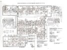
The Beomaster 1000 schematics is far too small to read it properly.

My question:
  • is there a STEREO/MONO switch? Could it be that the general circuitry around the MPX decoder socket shorts the L and the R outputs?
PS
Yes, there is one, - wires #7 and #8 may be shorted by the MONO button.

I just quickly measured across pins 8 (Left) and pin 9 (Right) of the TA7343AP and I'm getting a short :wtf:

There is definitely no bridging from the L to R tracks anywhere between there and short distance to the output caps, I've been over it with magnifying glass.

Therefore its looking distinctly like a defective IC but I don't have time to pull it this evening, will update as soon as have. I've a bag full of spare ones at least if it is that what has tripped me up (I tried a couple and they definitely do NOT measure short across those pins).
 
Did you try to measure the connectivity on the submodule's socket between pins 2 and 3 - with the FM button pressed (and your module removed)?
 
Back
Top Bottom