• The move to the new server is done. There are some software and database maintenance updates in process. This has us passing the hat around to help out. We appreciate any donations. Seriously, even a dollar helps. The payment page may be found here - https://www.audiokarma.org/support.html

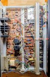
Tandberg TR 2055 with blown L channel output transistors

montesa

New Member
I have always wanted to get into electronics and have been too scared to try. I recently tried to resurrect a Harmon Kardon Hk 670 receiver I had in college (40 years ago) that had a bad left channel but after studying its design and construction (and ridiculous wire wraps) decided I had better leave that to a professional if I ever wanted it to work again. It's now at Marconi electronics in Burbank. I though I would take on another project that was in bad shape that I couldn't likely make any worse. I bought a Tandberg TR 2055 for $50 with a blown left channel. The output transistors are shorted but so far all the resistors I could test in the board are OK. This receiver is diabolically designed like a puzzle box and it seems worse to work on than the Harmon Kardon.

I have a basic question. How the heck do you remove the heatsink with the output transistors? The transistors don't seem to be in a socket but rather are soldered directly to the wires. The board doesn't want to come out vertically even with all the screws removed. I was hoping there was was a way to remove the back of the receiver and access the hex nuts that hold the transistors but the back can't be removed very far at all due to all the wires which are soldered to various locations -speakers terminals etc. Even de soldering the transistors seems like it would be pain in the current location. Should I just try to cut the legs of the transistors, though by doing that I'd probably wreck the crimps on the ends of the wires.

Is this just a horrible receiver to learn on? I have zero skills. I can barely solder.
 

Attachments

  • IMG_20261028_233319417.jpg
    IMG_20261028_233319417.jpg
    141.4 KB · Views: 20
Register to hide this ad
While I don't have experience with this particular model, those that I have worked on have been pretty tough. Defo not for a beginner.
 
Have a TR-1055 apart on the workbench was a puzzle figuring out what held the back panel on. On this older model there two vertical screws on the bottom of the of the back piece with the speaker terminals on it that blocks access to the output transistor screws and also had to remove the turntable grounding screw to free that panel. Took some discernment to figure that was who on the antenna terminal end of the unit was holding tight to that back panel. Some receivers are easy to work on, unfortunately Tandberg not one of them. That back panel in the picture is flipped around tucked along the left side of the receiver. Had to pop the tuner board free to access the screws to the power supply boards so I could move them to get the amp boards free. Unfortunately transistor pin wires need to free and transistors removed to pop free amp boards in this model.

IMG_20261029_060840_892.jpg
 
I did a 2040 several years back, from what I recall the insides of that looked about the same as this.

The transistors do solder directly to the wires, the metal "thing" is both what the screws thread into, and the clamp for the bias transistor if I remember right. I don't remember having any special issue getting the transistors out, maybe its just a couple screws up from the bottom holding the heat sink? I know I did not remove the board or the back panel.

and yeah this wasn't the easiest thing to work on. I did a 2080 at the same time, and despite being way more "full" inside, I thought it was less difficult to deal with. That service manual actually had instructions for how to get to things, the rest was mostly obvious, couple screws and each channel's amplifier board came right out.

Make sure you check the driver transistor for shorts. If thats bad, keep going backwards until you get good parts otherwise this will just blow up again the first time power is applied.
 
I worked on a TR 2045 (see here). The TR 2045 is part of the 3rd TR 20XX series and I found it easy to work on compared to my Yamaha CR600 (the first piece of gear I worked on). It seems they improved things on the 3rd series as the power transistor wires plug into the PCB. So I was able to remove the heat sink with wires and then desolder. I was able to access the top and bottom of the power amp / protection board to recap it without taking anything apart.

@montesa mine also had blown output transistors on the left channel when I got it. I was never able to 100% figure out the root cause but my trimmer was way out of spec so you might want to check R825. Also Frako capacitors are known to go bad. Is C807 (the yellow axial) a Frako?

Edit: I remember being intimidated by the thought of desoldering the pins from the output transistors (I did have to do 2 in place as the connectors were shared with the other channel) but it was not difficult.
 

Attachments

  • tr2045_heatsink.jpg
    tr2045_heatsink.jpg
    267.4 KB · Views: 13
  • tr2045_access.jpg
    tr2045_access.jpg
    314.3 KB · Views: 14
Last edited:
Back
Top Bottom