• The move to the new server is done. There are some software and database maintenance updates in process. This has us passing the hat around to help out. We appreciate any donations. Seriously, even a dollar helps. The payment page may be found here - https://www.audiokarma.org/support.html

Tandberg TR2040 balance pot question

gjcr5121

New Member
Hi, I have a TR2040 that has the balance pot shaft off. The axle (grey plastic center bit) is flat with the metal housing. I tried to glue a bit of plastic to the grey center bit but it won't stick when turned.
I would like to replace it with a new one. What specs should a replacement balance pot have?
Thanks in advance.
G.

Some background info: I picked up this TR2040 from an online auction site some weeks ago. Condition was unknown but lights worked so it seemed. I thought why not give it a try. They really look sophisticated and you don't see them very often.
Connected the dim bulb tester and a cheap speaker; only thunder no lightning. At least it made noise.
When the case was open I could see that someone had been in there before. The resistors at the tape inputs were bypassed with wire. This isn't original is it? There were a couple of frako caps and some bulging plessey caps so I decided to replace them all. Tuner section was left alone and so were the large siemens caps.
Tandberg is working fine now, thunder has gone. It is only that the balance is off center. That is, until the balance pot is changed ;-)
 
  • Like
Reactions: mbz
Register to hide this ad
Maybe post a pic showing the damage etc... Finding a replacement can be a PITA, need to have the correct solder connections
(pins, lugs) also shaft length, diameter, centre dentent? stepped? flat shaft or knurled.... Would guess a panel mount...
Start with the bourns data sheet, try and identify the key lengths etc.
https://au.mouser.com/datasheet/2/54/PDB18-1013655.pdf
 
IMG-20210518-081420.jpg
 
  • Like
Reactions: mbz
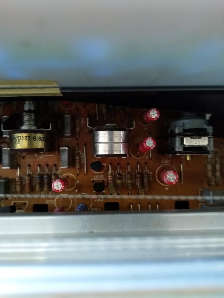
Thank you mbz. This is how it is. As you can see the knob and shaft are loose.
I was able to scrape off the glue remains with an x-acto knife , use a 2mm drill and very carefully make a small hole in the center of the axle.
With a small torx screwdriver I could turn the shaft a bit to the left and checked with headphones for center alignment.
Solved :-)
(I never use the balance control anyway)
 
  • Like
Reactions: mbz
These are the bridged resistors. I have unsoldered the wires and as one would expect the input level on the tape inputs is slightly lower. I will leave them unsoldered.
IMG-20210510-100043.jpg
 
(I never use the balance control anyway)
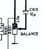
Suspect most people don't (need to) use it. If the part is unreplaceable, a common hack is to replace the pot
with 2 fixed resistors, 2x12k (or is it 2x25k?) would be suitable in this case, one from input to wiper(middle pin), the
other from wiper to GND, replicating,
upload_2021-5-19_7-32-21.png

That way the balance would be permanently set to centered. The original pot can remain inserted for appearances.
Just need to snip off the pins so the resistors can be inserted. I'd suggest still doing a parts search.

EDIT: maybe something like this from mouser, 652-PDB182-K420K203B 20mm shaft, knurled no centre detent. Would need to check pin spacing
 
Last edited:
The original pot has a long thin shaft, something like 3" long and maybe 1/8" diameter. Replacing them with off the shelf pots while still having front panel control access will take some doing.

Should be able to sub a balance control from any of these models, I believe they are interchangeable: TR 2025, 2030, 2045, 2060.

John
 
Thanks! Maybe in future I will fabricate a new shaft but for now i will leave it like this. A picture is owed:
WP-20210522-12-53-10-Pro.jpg

Yes there are better looking examples about, but this one is mine :-)
 
This is an older thread, but I still thought I would post because I have a fix for some cases of the TR-2025/2040 balance pot issue. Note that this fix is effective only if the gray socket section into which the rotator rod fits is generally intact, allowing, of course, for stress cracks that can be repaired by applying the technique described below. If sections of this housing have broken off in any way, it is not viable. It seems like this pot may have been designed for various applications, hence the detachable socket/rod arrangement that might accommodate different lengths. The problem is that the serrated plastic socket cracks over time due to torque stress, leaving the attached rod/shaft unable to rotate the pot. To fix, follow these steps:

1.) Detach the rod from the pot completely by pulling straight out.
2.) Allow it to rest inside the chassis at an angle temporarily, so that the threaded tip of the rod is accessible.
3.) Rotate the rod with the outer knob slowly while applying a coating of two-part clear epoxy resin. The viscosity of the resin is such that it will hold its position as this is done.
4.) Carefully reinsert the rod into the socket.
5.) Apply a second resin coating to the outside of the socket to mitigate any tiny cracks that may be present.
6.) Despite any "quick set" claims, wait a total of 72 hours for a full cure.

There are some caveats to the process that can't be ignored. First, you must insure that you start with the pot in its "center" position, which may not be easy to find. Second, don't fool around with other high-strength glues that you think might also work, such as Pliobond or cyanoacrylate/"Superglue." Believe me, they will not handle the necessary torque. Finally, this job is not easy, as it requires a certain amount of patience and dexterity. You are likely to become frustrated at first, but know that a fix is indeed possible.
 

Attachments

  • TR-2040_B-pot_fix.jpg
    TR-2040_B-pot_fix.jpg
    98.6 KB · Views: 11
Last edited:
Back
Top Bottom