• The move to the new server is done. There are some software and database maintenance updates in process. This has us passing the hat around to help out. We appreciate any donations. Seriously, even a dollar helps. The payment page may be found here - https://www.audiokarma.org/support.html

Technics RS-1500 FF and REW do not stop

Not that old

New Member
Hi,
I bought a Technics RS-1500US some time ago and found a few problems.
  • FF and REW do not stop when pressing STOP.
  • The left and right tension arms have different end positions. The left one stops in the top position but the right stops about ½” lower.
  • The left tension switch S19 was erratic.
PLAY works fine and stops when pressing STOP.
I have repaired the S19 tension switch and it now works OK.
FF and REW only be stopped by releasing the tension arms.
I have recapped the entire unit and hoped this would resolve the FF and REW issue, but unfortunately it did not.
I do not understand why the tension arms have different end positions, as the brackets cannot be adjusted as far as I can see.
Thankful for all kinds of advice and help.
 

Attachments
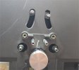
  • Tension arms 2.jpg
    Tension arms 2.jpg
    12.2 KB · Views: 5
Last edited:
Register to hide this ad
You might need to rebuild the brakes? Thin cork clued to the metal band and then some fine adjustments.
 
(EDIT... for some reason, I can't attach any files or pictures. I'll try again later) If you have the SM and Schematics, you can look it up yourself.

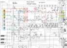
Here is the schematic of the Main Control Board.
  • The FF (S13) and REW (S14) buttons come from the Key Switch board into the connector B (pins 4 & 5) on the Main Control Board (see schematic)
  • The switch closures go through some discrete logic and come out on connector D (pins 4 & 3) (see board layout)
  • When you press either the FF or REW button, the signal on connector B should go from 5v to 0v when you press the button
  • With your DMM, check the voltage on pins 4 and 5 as you press the button down to see if the voltage changes.
  • If it is good, the do the same check on connector D pins 3 and 4 (these may be the opposite logic, 1=H, 0=L)
I have a few questions to help isolate the problem:
  1. If you press the FF button, does it start fast forward?
  2. If you press the REW button, does it start rewind?
  3. If you are in FF and you press REW, does it switch to rewind?
  4. If you are in FF or REW and you press PLAY, does it stop winding and go to PLAY?
 
Last edited:
The brakes can be adjusted there’s a procedure in the service manual if you spin the reel motor clockwise and anticlockwise do they feel any different? Do this with power off is there any evidence of internal tampering with the machine?
 
(EDIT... for some reason, I can't attach any files or pictures. I'll try again later) If you have the SM and Schematics, you can look it up yourself.

Here is the schematic of the Main Control Board.
  • The FF (S13) and REW (S14) buttons come from the Key Switch board into the connector B (pins 4 & 5) on the Main Control Board (see schematic)
  • The switch closures go through some discrete logic and come out on connector D (pins 4 & 3) (see board layout)
  • When you press either the FF or REW button, the signal on connector B should go from 5v to 0v when you press the button
  • With your DMM, check the voltage on pins 4 and 5 as you press the button down to see if the voltage changes.
  • If it is good, the do the same check on connector D pins 3 and 4 (these may be the opposite logic, 1=H, 0=L)
I have a few questions to help isolate the problem:
  1. If you press the FF button, does it start fast forward?
  2. If you press the REW button, does it start rewind?
  3. If you are in FF and you press REW, does it switch to rewind?
  4. If you are in FF or REW and you press PLAY, does it stop winding and go to PLAY?
Starting with your questions.
1. FF button starts FF. 2. REW button starts REW. 3. If in FF nothing happens when pressing REW. 4. Pressing PLAY has no effect on FF or REW. 5. If in REW nothing happens when pressing FF. Only releasing the tension arms stops FF and REW.
Then to checking connectors B and D.
Pins 4 & 5 in D hover around 0V whatever I do. Before and after pressing FF or REW. Same goes for B pins 3 & 4.
I am measuring ground to pin, not pin to pin. I am a mecanical guy, unfortunately not an expert in electronics, so I need all the help I can get.
Very glad you looked into my problem.
 
Thanks for your responses. What kind of test equipment do you have (multimeter, oscilloscope, etc.)?
Can you read a schematic diagram?
  1. On the left is the Key Switch Board containing all of the transport keys
  2. On the right is the Main Control Circuit Board that contains the logic for the transport switch control
  3. I have highlighted the main signal paths for the FF (red), REW (green), and STOP (blue) controls
  4. The top part of the schematic is mainly the logic that reads the tape transport keys (just momentary contact switches) and generates signals to output on connector "D"
  5. In your response to my questions 1 & 2, both the FF and REW switches start the FF and REW motor functions so we know the push switch works and the signal gets through the primary signal path
  6. You said that pressing STOP, PLAY, or other buttons does not stop the FF or REW operation
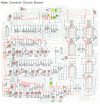
Could you please double check what you said below? (See the board layout for connector locations.)
  1. "Pins 4 & 5 in D hover around 0V whatever I do" - This should be "Pin 4 and Pin 6 on Connector B."
  2. "Same goes for B pins 3 & 4." - This should be "Pin 4 and Pin 3 on Connector D."
  3. Also, STOP (button should go to Connector B Pin 1.
  4. Since the switches are momentary contact on Connector B, you need to measure the voltage while you hold down the button and when you release the button.
  5. Sorry for the mixup. I think I got it right now.
1788102593556.png

1788103593232.png
 
Thanks for your responses. What kind of test equipment do you have (multimeter, oscilloscope, etc.)?
Can you read a schematic diagram?
  1. On the left is the Key Switch Board containing all of the transport keys
  2. On the right is the Main Control Circuit Board that contains the logic for the transport switch control
  3. I have highlighted the main signal paths for the FF (red), REW (green), and STOP (blue) controls
  4. The top part of the schematic is mainly the logic that reads the tape transport keys (just momentary contact switches) and generates signals to output on connector "D"
  5. In your response to my questions 1 & 2, both the FF and REW switches start the FF and REW motor functions so we know the push switch works and the signal gets through the primary signal path
  6. You said that pressing STOP, PLAY, or other buttons does not stop the FF or REW operation
Could you please double check what you said below? (See the board layout for connector locations.)
  1. "Pins 4 & 5 in D hover around 0V whatever I do" - This should be "Pin 4 and Pin 6 on Connector B."
  2. "Same goes for B pins 3 & 4." - This should be "Pin 4 and Pin 3 on Connector D."
  3. Also, STOP (button should go to Connector B Pin 1.
  4. Since the switches are momentary contact on Connector B, you need to measure the voltage while you hold down the button and when you release the button.
  5. Sorry for the mixup. I think I got it right now.
View attachment 3826659

View attachment 3826665
Hi,
Thank you for the update. I have a Fluke, Millivoltmeter, Signal generator and an Oscilloscope (just learning how to use the latter).
I can read a schematic in a very amateurich way and can follow your marked instructions.
As for the measured values, it is still the same. With PWR ON and tension switches S19/20 activated (arms down), STOP button ON or OFF, pins 4 & 6 on Connector B read 0 V.
The same goes for pins 3 & 4 on Connector D ( 0 volts).
Am I wrong in thinking that pin 2 in connector D should have 5 Volt? It says 5V on the diagram. I only get zero there when I test it.
Looking forward to further info and troubleshooting from you.
Regards
 
Last edited:
Am I wrong in thinking that pin 2 in connector D should have 5 Volt? It says 5V on the diagram. I only get zero there when I test it.
Yes you should get +5V at pin2.
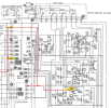
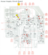
Follow Pin 2 back to the source of the +5V (red dotted line), TR608 collector.
Check the voltage there. Also check the base and emitter voltages. They should be as shown on the schematic and board layout.

1788190755992.png
1788191396926.png
 
Back
Top Bottom