• The move to the new server is done. There are some software and database maintenance updates in process. This has us passing the hat around to help out. We appreciate any donations. Seriously, even a dollar helps. The payment page may be found here - https://www.audiokarma.org/support.html

Technics SA-202, Replace STK0029 with STK0050 (discrete circuit)?

Moncho

Member
Hi guys,
happy to be here, but I need some guidance from more experienced people.

I've just bought a Technics SA-202 integrated amplifier, this particular model has an emotional value to me because it was the "radio" that my father had back in the day.
The integrated amplifier is in general in a very good condition but is over 40 years old and have some issues, included the most common one, one channel is dead. Following the information in the manual service, I've measured here and there and it's pretty clear, that the power-amp STK0029 chip is blown.

As you all know, this chips are not built anymore and what you find in internet are used ones or knock offs. In any case, there is no guarantee that is going to work as intended.
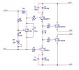
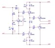
I found here in this thread, someone that made a great job designing a STK0050 replacement with a discrete circuit. so, here comes my question. Can I also use this replacement design (made for stk0050) to replace my STK0029?
I found the STK0029 datasheet (file attached) and there I can see that the circuit topology is different, but the general characteristics are the same for both except for the "maximum supply voltage".

Maximum supply voltage
STK0050: +53/-53
STK0029: +37/-37

So again, can I use the replacement design (made for stk0050) to replace my STK0029?

Thanks a lot guys, I'll be happy the read all your comments.
 

Attachments

Register to hide this ad
Electrically it’s equivalent but you have to verify that the stk-0050 that we designed with the integral heatsink will fit.
Thanks !!!
I want to design my own PCB using SMD components, so I can still use the original heatsink. That shouldn't be an issue, right?
 
Thanks, but 60 bucks for a module? I prefer to build my own PCB, but the dimensions and overall form will be a very good guide.

The other module (stk-0050) that @rcs16 is speaking of is available pre-assembled for about the same cost, or you can get complete parts kits, or just the PC board.

I used two of these more complex modules to restore an SX-780 for someone who inherited it from his father and the emotional attachment you speak of justified the extra cost and piece of mind that it would work for many more years. Nice high quality part.

Cost, Maybe it is supply and demand?

Crap shoot on knockoffs that may fail and possibly take your speakers with it.
Finding NOS genuine parts is possible with patience.
Another crap shoot purchase "good" used ones.

I think it is great that you want to design and build from scratch. Please consider sharing with the community.
 
Last edited:
The other module (stk-0050) that @rcs16 is speaking of is available per-assembled for about the same cost, or you can get complete parts kits, or just the PC board.

I used two of these more complex modules to restore an SX-780 for someone who inherited it from his father and the emotional attachment you speak of justified the extra cost and piece of mind that it would work for many more years. Nice high quality part.

Cost, Maybe it is supply and demand?

Crap shoot on knockoffs that may fail and possibly take your speakers with it.
Finding NOS genuine parts is possible with patience.
Another crap shoot purchase "good" used ones.

I think it is great that you want to design and build from scratch. Please consider sharing with the community.
Hey @mrk229 you are right, the peace of mind and emotional attachment justify the price, but I live in Germany and import those, plus taxes, it will be very expensive at the end. As I said, I am fully capable of design a PCB that fit my needs. I just need time for it, but if go for it I'll share the design here.
Thanks again, is nice to have people that appreciate this "little things".
 
Hi Guys,

I'm about to build the original design, going to SMD was just to much effort. Anyway I still have a question and it's, how do you set a proper bias current?
I'm absolutely new in this and I think that I have to measure the voltage at the base of Q5, which will change if the variable resistor value changes. But what voltage value should I have there?
A detailed explanation or literature would be welcomed, do you extract some information from the datasheets to get a operation point for the transistor and then it's all just math? I'd love to learn and so not to have to bother you guys anymore and maybe help to someone else in the future.
@rcs16 @punchback

PS: sorry that I mention you guys directly, but I'm sure that you have the answer :)

Thanks in advance and have a nice day.
 
Last edited by a moderator:
I think with 20 mA measuring voltage across the emitter resistors you'll be fine. (mV/ohm=mA). Bias current is usually set that way. You monitor the voltage across one emitter resistor.

Or, take an oscilloscope and check for crossover distortion. But 20 or 25mA bias current is my choice when I don't have manufacturer data.
 
Last edited:
Look at the original stk spec, they say typ 40mA,80 mA maximum OPS bias/idle current which is fine to use for the discrete versions as well.
 
Look at the original stk spec, they say typ 40mA,80 mA maximum OPS bias/idle current which is fine to use for the discrete versions as well.
Hi @rcs16
Thanks for your reply. The 40mA to 80mA should flow flow through R3 and R4 in your design? or also through R1 and R5?
What about Q5? how can I be sure that he is ok?
 

Attachments

  • stk0050.JPG
    stk0050.JPG
    44.3 KB · Views: 29
I think with 20 mA measuring voltage across the emitter resistors you'll be fine. (mV/ohm=mA). Bias current is usually set that way. You monitor the voltage across one emitter resistor.

Or, take an oscilloscope and check for crossover distortion. But 20 or 25mA bias current is my choice when I don't have manufacturer data.
Hi @elnaldo
Thanks for your reply. In this circuit I do not se any evident emitter resistor :/
 

Attachments

  • stk0050.JPG
    stk0050.JPG
    44.3 KB · Views: 19
OPS Bias current runs through Q1,4 connected to the external resistors 0.22ohm,in the sx-780 case, mounted on the mother pcb.
You measure bjt with your ohmeter in diode test mode.
 
I think with 20 mA measuring voltage across the emitter resistors you'll be fine. (mV/ohm=mA). Bias current is usually set that way. You monitor the voltage across one emitter resistor.

Or, take an oscilloscope and check for crossover distortion. But 20 or 25mA bias current is my choice when I don't have manufacturer data.
Hi @elnaldo
Thanks a lot. That is my case, I do not have any manufacturer data related to bias current, because in the SA-202 the complete amp section is packaged in the original STK0029. I have found the emitter resistors (R627 and R628 in the attached picture). I will measure the voltage across those resistors (at each end of each resistors, so the voltage drop). I will also connect an oscilloscope at the output and check for any distortion, maybe experiment a little, but if the current across each Re are aprox. 25mA as you say and I do not see any distortion, then I'll leave it ... if it works do not fix it will applied in these case for me. I do not want to burn or stress anything if it's not necessary.
I hope that what I have just explained make sense, if not please correct me.
Thanks again :)
 

Attachments

  • Re_for_bias.JPG
    Re_for_bias.JPG
    100.9 KB · Views: 25
R627,628 are part of the zobel network, no DC current flows. In your posted schematic, it shows that the emitter resistors are integral to the STK so you have no means to measure the idle or ops bias current
If you use stk-0050 then you will need to add the 0.22-ohm emitter resistors
 
Thanks, but 60 bucks for a module? I prefer to build my own PCB, but the dimensions and overall form will be a very good guide.

This is a great idea, @Moncho ! You'll learn a lot, AK members will have the opportunity to help you answer questions, you'll end up with a working replacement you are proud of, and we'll all have one more option for solving this problem.
 
Hi @elnaldo
Thanks a lot. That is my case, I do not have any manufacturer data related to bias current, because in the SA-202 the complete amp section is packaged in the original STK0029. I have found the emitter resistors (R627 and R628 in the attached picture). I will measure the voltage across those resistors (at each end of each resistors, so the voltage drop). I will also connect an oscilloscope at the output and check for any distortion, maybe experiment a little, but if the current across each Re are aprox. 25mA as you say and I do not see any distortion, then I'll leave it ... if it works do not fix it will applied in these case for me. I do not want to burn or stress anything if it's not necessary.
I hope that what I have just explained make sense, if not please correct me.
Thanks again :)
In a real STK, you can't adjust the bias (or idle current). In a replacement module, you can. That's one of the advantages of those replacements.

Emitter resistors are the low value / high wattage resistors (usually from 0.18 to 0.47 ohm) connected directly to the output transistors emitter.
 
Thanks a lot for all your answers.
I'm planning to buy this as emitter resistors, but not now. I don't want to pay $18 for shipping, only to buy a couple of resistors, so I will gather more "useful stuff" and make a bigger purchase.
I'll just need to be creative to make them fit and look "professional". Sadly I didn't have them in consideration at the moment of make the PCB and therefore jut used the original design from @rcs16. I'll find a way to make it work :)
 
Thanks a lot for all your answers.
I'm planning to buy this as emitter resistors, but not now. I don't want to pay $18 for shipping, only to buy a couple of resistors, so I will gather more "useful stuff" and make a bigger purchase.
I'll just need to be creative to make them fit and look "professional". Sadly I didn't have them in consideration at the moment of make the PCB and therefore jut used the original design from @rcs16. I'll find a way to make it work :)
Cutting a pcb trace and soldering the resistors on the solder side of the board, directly at the other components solder pads, is usually a neat fix.
 
Back
Top Bottom