• The move to the new server is done. There are some software and database maintenance updates in process. This has us passing the hat around to help out. We appreciate any donations. Seriously, even a dollar helps. The payment page may be found here - https://www.audiokarma.org/support.html

Technics SA 202 with a dead left channel

Adippell

New Member
Hello Ak’ers,

Ok, so this is my first thread, aside from the introduction so please bear with my ignorance.

I have a Technics SA-202 that I purchased at the Salvation Army for $15. It had a blown fuse on the back panel for the left channel. I replaced the fuse, but this didn’t rectify the issue. So onward to my first attempts to diagnose the problem. To start I took off top and bottom panels and de-ox’d the pots. I inspected the board and didn’t see any obvious burned or blown parts. I checked inputs (FM, AM, Phono, and Tape). There is no sound at all coming from the left channel, not even a hiss at full volume, from any inputs. I made sure the balance was centered.

So this is when I discovered AK, google searching this unit has brought me here and what a resource it has already been!

After reading through several threads, but none related to exactly to this unit, it seems the most likely issue is the power pack (STK0029). I have a fluke multimeter, so I started with the capacitors and all seem to power up and discharge. I read on a related thread to use the diode function to test the power packs. It was a thread for a SA 101, and Ak’er wd409 said “you can do a diode test on the power packs, red probe to pin 1, black to pin 10, then switch the leads to the opposite sides, then test 2 and 9 as well, and then switch it. one polarity should say OL and one should say around 0.600 give or take, the one that shows 0.000 is the dead one. assuming it has 10 pin power packs like the 303 and 404 have.”

So I started to test and didn’t get any of the readings suggested. Obviously it’s a different power pack so the values would be different. This is what I found:


The left power pack (when facing the unit) reads “OL” no matter what pin combo I used (1 & 0, or 2 & 9) and regardless of polarity. Then when powering the unit down the meter would read 1.4 using the + on 1 & - on 0.

The right pack reads 1.7 and OL respectively, then 2.62 (and OL on the other polarity) when the unit is powered down.

One other issue is when the test speaker is hooked up to the right output and the unit is powered on initially there is a loud popping sound. If the unit is turned off and then turned back on after the initial there is no popping sound. If the unit is off for approximately 5 minutes and then turned back on the pop comes back.

So my thoughts are that the left pack is bad and needs to be replaced. But before I start dismantling the heat sink and break out the soldering iron (and ordering parts from eBay) I’d like advice from those who have more experience. I have no idea what is causing the popping.

Thank you to any and all who respond to my query. I promise to follow up on any advice given and report back any results.

** Posted prior to the reset, Ak'er suggested I disconnect the left power pack and see if audio comes through on the headphone jack. I discovered that my soldering iron is DOA, and have ordered another one from Amazon. So that test will have to wait a few days. I did try the headphone jack as I hadn't thought of trying that output, same as the speaker output. No sound at all.
 
Register to hide this ad
Hello. I see the SA-202 doesn't have a protection-muting relay, so the circuit could have some muting circuit based on some timing capacitor. Perhaps that's the difference between powering ON after some minutes, when some capacitors were discharged.

Anyway, I'd concentrate on your problem first. The Left STK seems gone. Please, disconnect any speaker from the unit, and check if the output protection fuses are OK. If so, do a brief test, measure DC at the speaker terminals, with the speaker set active, and volume knob to zero. You should have some mV, less than 20, on the good channel. The bad channel could be Zero, or 20 to 35V. If you have high voltage, no more doubts, the STK is blown. (anyway, your DMM readings indicate it's faulty.) I suggest you to check or replace the transistor between the STK and the AN7060 preamp. If teh STK is blown, it probably damaged the transistor too. Check the resistors around that area, all the resistors connected to a shorted STK, just in case.

Also, before installing a new STK, check supply voltages at the V+ and V- pins, and DC offset at the signal input pin (it must be zero, if you have high voltage at the signal input pin, something is still wrong)

The headphone's output is taken from the STK output, and after the protection fuses. If the fuses are blown, no sound. DON´T connect headphones or speakers before verifying the DC at the output. You can feed 30V to your headphones or speakers. (actually the headphones will have a limiting resistor that will burn under that voltage, check that resistor on the headphones connector board, if it looks burned. Measure both channels, they must match resistance)
 
Elnado,

Thanks for the reply. I went to test it today and realized that the fuse I got from radio shack was actually 3.0a 250v instead of 3.0a 125v. I hunted around the Internet and made some calls locally but haven't found any replacements yet. So to test I have just been switching my 1 good fuse back and forth...

Anyway, the right (operational) side output is testing at 18.6 mV, the left side is testing at -48 to -50 mV fluctuating.

For the transistor, I only found one I could trace to the power packs. I tested OL on the mV setting and .633 on the V setting.

All of the resistors I tested in the area seem to be ok. I may have missed some but the only schematics I have been able to locate online are blurry to the point of uselessness.

I haven't ordered the new STK yet, and I'm still waiting on delivery of my new soldering iron. If I am dismantling and replacing the left STK should I just order 2 and replace both while I'm in there?

I will check the DC output prior to doing any installing.

Thank you for your help on this, it's the first time I've played around with circuits in many years and even then it was at a basic level. You instructions have been helpful and easy to follow.

I will update again once I get to the next steps.
 
Do NOT buy a new STK, because they are all fake - the original part hasn't been in production since the 80s. Fakes will blow up - catastrophically - taking your speakers with them. If you can confirm the STK is bad (which is likely) then your amplifier is FUBAR, and destined for the scrap yard. This amp doesn't deserve your attention anymore, as it simply isn't good, cannot be fixed, has no useful spare parts, and zero economical value. Cut your losses and move on.
 
Well crap...
I won't toss it just yet. And if it's true that all the STK's are fakes then the working one might have some value to someone. And if I can come across some other unit that has the same STK maybe I can fix this one. Anyway junking it seems to harsh when I still have garage space for it...
 
Down here in buenos Aires the situation is different. Those units are expensive, you can easily get $300 for a working one, and I replaced several STK modules and all of them are working until today

If you decide to fix it, Don't worry about the fuse. 3A is OK regardless f the voltage.
 
Down here in buenos Aires the situation is different. Those units are expensive, you can easily get $300 for a working one, and I replaced several STK modules and all of them are working until today

If you decide to fix it, Don't worry about the fuse. 3A is OK regardless f the voltage.

Then the real question is where do you get good and genuine STK modules?
 
Couple of ways to go here, first is to find a unit with the same problem, i.e. one bad channel and take the two and make one. The other way is to use a fake STK chip, yes some are bad, but some do work, may have to order several to find a good one.
 
I only use fake ones! !! Perhaps I'm lucky, but they usually work without issues. I know people blame those chinese copies, but it seems to be the only solution for this units...
 
Thanks everyone for the input.

I've been poking around on the Ebay a bit more since Zoom alerted me to this whole fake parts thing. I found some guy out of New York selling under Joeoldaudio. His STK looks exactly like the ones in my unit and is claiming it came from a parted out SA-202. Looking at his Ebay shop it looks like he sells mostly parted out vintage gear and softballs (which I find strange and hilarious for some reason). So I'm hoping that this is a real and working part. He's selling it for $18.99 (free shipping in the US) which is higher than the fakes. But for $20 it's worth a shot maybe?

Anybody have experience with this seller? At any rate it seems my best option to keep the dream of tinkering on this unit alive.

Now I just need to try and remember my ebay log in. Haven't bought anything there in quite awhile.

Thanks again everyone contributing to this thread, your advice is appreciated.
 
Oh, and he has 3 of them. So I'm still wondering if I should replace both while I'm in there or leave the working one alone.

Thanks
 
leave the working one alone, but you could buy a spare one, just in case.. $20 Insurance, and a 3rd life for your amp. ..
 
Well I received the STK in the mail today. It looks as advertised, here's to hoping it's not dead. It came with the back coated in the old thermal paste and the pins look like they could benefit from a good cleaning. It's been a while (more than a decade) since I've soldered anything but speaker wiring, so I bought I crap DVD player from Salvation Army for $5 to practice de soldering and soldering on.

So between prepping the STK and getting to the point I'm comfortable soldering on something I want to be functioning it may be a few days before I can report if this fix worked out.

Elnaldo, since you've done a few of these... When removing and installing the STK do you somehow remove the heat sink fin above the STK or just sort of angle it in? I'm sure you know what I'm talking about but I can provide photos if needed.

Thanks again everybody for all the help. I'm into this receiver for about $40 so far. If this repair works I will be very happy indeed.
 
Well I received the STK in the mail today. It looks as advertised, here's to hoping it's not dead. It came with the back coated in the old thermal paste and the pins look like they could benefit from a good cleaning. It's been a while (more than a decade) since I've soldered anything but speaker wiring, so I bought I crap DVD player from Salvation Army for $5 to practice de soldering and soldering on.

So between prepping the STK and getting to the point I'm comfortable soldering on something I want to be functioning it may be a few days before I can report if this fix worked out.

Elnaldo, since you've done a few of these... When removing and installing the STK do you somehow remove the heat sink fin above the STK or just sort of angle it in? I'm sure you know what I'm talking about but I can provide photos if needed.

Thanks again everybody for all the help. I'm into this receiver for about $40 so far. If this repair works I will be very happy indeed.

I think I don't understand what fin you are referring to. But I remove the whole old STK, and the new one fits in place, I never removed or added any part to them, or re-used any part of the old STK.

The STK back is a flat and smooth metal piece. It must be clean, with a thin layer of new thermal paste.

Just a few tips I've learned the hard way: To remove the STK, you need all the pins absolutely free. What I do sometimes, suck the solder with a solder sucker, pin by pin, then get the rest of the old solder with a solder wick, embedded or wet with solder flux. To free all the pins, I use a magnifying glass an the hot solder tip to push them if they still have some solder, to have them free in the middle of the PCB hole.

Some other times, when I'm 100% sure the STK is bad, I cut the pins before desoldering, and then I desolder the pins one by one, pulling with some small pliers while heating the solder. This in MUCH easier and you save the PCB traces.

Also, I check supply voltages, continuity to ground, and DC at the signal pin input before fitting the new STK. The V+ and V- pins shouldn't have any continuity to ground (unit OFF, unplugged)

Here is a pict of an STK I removed last month. From a Technics SA-203

OLD STK:
P1130517.JPG


Old and New, side by side:
P1130519.JPG


P1130520.JPG


Checking supply voltages before installing the new STK:

P1130521.JPG


New STK installed on the heat sink, not soldered yet:
P1130522.JPG


Working. The black box on the back, with banana connectors, is a speaker protection circuit, I always use it when I connect an Amplifier that I don't trust.
P1130529.JPG
 
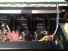
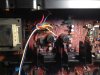
So I have (hopefully) uploaded a top view and side view photo of the area where the STK's are. Although most of the board is spacious this particular area is pretty tight.

I hoping that I don't have to remove the whole board from the housing and even then I wouldn't be able to remove the heat sink withou detaching the other STL and the transistor.

Also, looking at the underside only 6 pins are soldered in, the other 3 on each side. I don't know which pins are which for testing V, continuity, etc.
 

Attachments

  • image.jpeg
    image.jpeg
    84.1 KB · Views: 51
  • image.jpeg
    image.jpeg
    85.5 KB · Views: 50
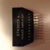
Here are 2 shots of the new STK post cleaning. Removed thermal paste with Arcticlean and deoxit'd on the pins

image.jpeg image.jpeg
 
It's a good idea to check the pre-drive stages for any issues before installing any modules. The bad rap the modules get is most guys don't check the circuits out before replacing the module. Also getting good heat transfer between the module and heatsink. Many modules will die after several hours of operation. this is due to poor heat transfer. The plastic wings with the attachment holes can keep the module from making close contact with the heatsink. I'll use a flat surface and 400 wet/dry to sand the back of the module and make a true surface. This insures good thermo bonding with minimum paste. All reasons for the counterfeit rap.

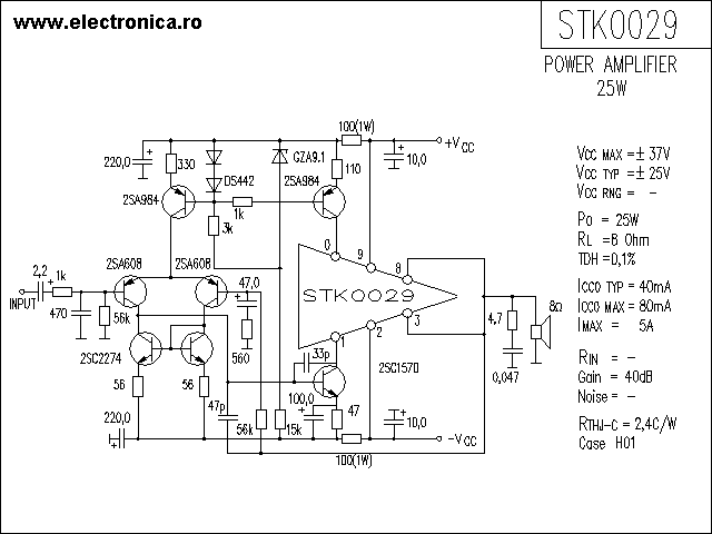
STK-0029 Datasheet
 
Last edited:
+1, check any transistor in the previous stage, as stated, V+ and V- supply voltage, and DC at the signal input pins (pin 10 and pin1). It must be "zero" V at those pins, or just a few mV.
 
Back
Top Bottom