• The move to the new server is done. There are some software and database maintenance updates in process. This has us passing the hat around to help out. We appreciate any donations. Seriously, even a dollar helps. The payment page may be found here - https://www.audiokarma.org/support.html

Technics SA-700 ‘smokin’ hot

dustmaker

Active Member
I am on a journey and I need some guidance from the experts on a very nice looking Technics receiver. It only has one known minor issue......when you turn it on its start smoking

I put it on a 100watt DBT and it still smokes. There are 4 resistors on the left channel that are all burnt. Two on the right channel are slightly discolored but not by much. In order to work on this unit I have since added a variac adjusted to 60 volts along with a 60watt DBT.

I’m assuming a short but the DBT was dark

I replaced the 4 burnt resistors all on the left channel, and I replaced 4 transistors 2 on left and 2 on right as the manual seems to indicate these transistors must be done in pairs.

While testing it earlier, I had a short but the DBT was dark. After replacing these resistors and transistors, the DBT is now orange. I double checked for any metal bridging and my transistors are in the right orientation. I noticed that even with a 60watt DBT and 60 volts on the variac, one of my new resistors is already discoloring with the unit on for less than a minute

right now I suspect the bridge rectifier and/or one or both filter caps. I removed the rectifier and tested it separately with a DMM and it seems to be working ok but when it was in circuit it tested faulty on one diode. I tested filter caps with an ESR and one measured ok the other one says it’s good if cap is less than 25v, which it isn’t, so I’m guessing that cap is bad. I haven’t yet pulled the caps out to test on their own.

Am I on the right path in my journey?
 
Last edited:
Register to hide this ad
Just to clarify, I was testing the foil trails and detected voltage on the ground trail close to C702. What I don’t understand is why it seems to mainly affect the left channel, that’s where a bunch of resistors were cooked. Why wouldn’t both channels show similar damage?
 
This Technics has a 220μF 16v bi-polar capacitor (C903). I want to replace it. Should I stick with 16v or should I upgrade to 25v?
 
Last edited:
I cant help I am now just learning have you searched "Technics SA-700 audiokarma"
and found a bunch of old threads where people are talking about it and getting help
 
I cant help I am now just learning have you searched "Technics SA-700 audiokarma"
and found a bunch of old threads where people are talking about it and getting help
Thank you,
yes, I’ve looked at the threads and there is very little on the components and repairing. This unit apparently isn’t very popular here and either no one has experience with it or they choose to not dabble in it anymore. It is difficult to access some components without taking apart a significant part of the receiver. On the main board, the foil side is accessible to about half of the main board with a large metal frame blocking parts

it looks like I will be doing my journey on my own. I will document it as I go. I’ve already started so some I recreate where I can.

I’m sure after I’ve made an mistake someone will comment I shouldn’t have done that. Kinda like being married, good advice after the fact.
 
Thank you,
yes, I’ve looked at the threads and there is very little on the components and repairing. This unit apparently isn’t very popular here and either no one has experience with it or they choose to not dabble in it anymore. It is difficult to access some components without taking apart a significant part of the receiver. On the main board, the foil side is accessible to about half of the main board with a large metal frame blocking parts

it looks like I will be doing my journey on my own. I will document it as I go. I’ve already started so some I recreate where I can.

I’m sure after I’ve made an mistake someone will comment I shouldn’t have done that. Kinda like being married, good advice after the fact.

Poor you. I'll watch this thread, so that I can comment when you do something you shouldn't of.
 
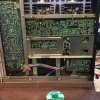
Attached photo shows bottom of receiver with metal bracket. It’s held by 10 screws. 4 from pcb to this bracket, 2 from transformer to bracket and 4 from frame to bracket. I could remove 9 and couldn’t figure out how to remove last screw. The screw head was underneath pcb and it went through bracket into frame. I could only access the screw threads. I solved the problem using a Dremmel and I cut a slot on the thread side of screw and was able to remove it using a small standard scewdriver

I had to remove all screws on back plate and pop out plastic pins to provide clearance to remove the bracket
 

Attachments

  • 65D3A372-20C1-4991-BBA2-DD4F934106DD.jpeg
    65D3A372-20C1-4991-BBA2-DD4F934106DD.jpeg
    164 KB · Views: 42
Last edited:
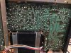
Here is photo of foil side with bracket removed. I’ve also removed rectifier diode and filter caps C701and C702. These caps are 15,000μF/63v with a 7/8” pin spacing. 40mm wide. I can’t seem to find an adequate replacement but I did order 80-ALT22A153DE063 from mouser. Instead of solder pins, it has flat male paddle type connector. Not sure if this will work or not but if I use it I will have to dremmel the pcb which I really don’t want to do

the rectifier is a SV15VB20 which I am unable to find but I did order a SV15B60. It appears that it should fit and work adequately.
 

Attachments

  • image.jpg
    image.jpg
    145 KB · Views: 34
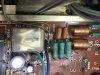
Another funky looking resistor, again on left channel. I don’t know if it’s just an accumulation of dirt/oils but it looks like it was bubbling
 

Attachments

  • image.jpg
    image.jpg
    123 KB · Views: 47
looks like you are definitely making some progress
one thing I have noted is a lot of people measure those pins which should have certain spec voltage and then go from there to narrow stuff down

about all I can tell you is to maybe check the output transistors
 
Which resistors are cooking when you turn on the unit? Using reference numbers (eg R100) from the schematic.
The ones most toasty are: R627, R629, R639, R703. I replaced the first 3 with 1/2 watt instead original 1/4 watt and R639 is already darkened while on 60 wattDBT for less than a minute
Upon further looking:
these look like they’re starting to melt: R639,R636,R912 - I know it doesn’t mark any sense
These are very dull: R618,R620,R622,R628.
These have crazing/minor surface cracking: R601 - R606
 
What voltages are you getting at base and emitter of TR613?

And on each leg of the regulator transistors (TR701 and 702)?
 
What voltages are you getting at base and emitter of TR613?

And on each leg of the regulator transistors (TR701 and 702)?
I don’t know at full power since it smoked even when on a 60 watt DBT. I added a variac adjusted to 60 volts and these were the voltages:
TR613 was B: +20v
TR702 was B: -27.4 E: -26.7 C: -30.2
TR701 was B: +22.4 E: +21.8 C: 30.1

correction: it didn’t smoke on 60 watt DBT, but the bulb was orange and R639 started to darken
 
What about R704 and 705?

And I'm assuming you already addressed the rectifier issues? And have good filter caps installed?
 
I don’t know at full power since it smoked even when on a 60 watt DBT. I added a variac adjusted to 60 volts and these were the voltages:
TR613 was B: +20v
TR702 was B: -27.4 E: -26.7 C: -30.2
TR701 was B: +22.4 E: +21.8 C: 30.1

correction: it didn’t smoke on 60 watt DBT, but the bulb was orange and R639 started to darken


Yikes on base voltage of TR613. Were the outputs on the left channel pulled and tested?
 
What about R704 and 705?

And I'm assuming you already addressed the rectifier issues? And have good filter caps installed?
R703 2.2 Ω - at 60 volt on variac showing 0.1 voltage drop
R704 2.2 Ω - at 60 volt on variac not showing any voltage drop
R705 22k Ω - at 60 volt on variac . 7.6 voltage drop
R706 22k Ω - at 60 volt on variac. 2.6 voltage drop
All the above are from my notes, I am unable to recheck right now.

Rectifier and capacitors are on order. They just shipped today

see comment #9 above on the capacitors
 
I think best to wait until you get done with installing new stuff before doing anything else. It would be interesting to see if the outputs are still good, or got taken out by whatever is going on.
 
Back
Top Bottom