• The move to the new server is done. There are some software and database maintenance updates in process. This has us passing the hat around to help out. We appreciate any donations. Seriously, even a dollar helps. The payment page may be found here - https://www.audiokarma.org/support.html

Technics SL-1350 Rebuild Thread

Crumbs

Member
Ever since we put a new head shell in, hit play and the previously dormant unit started smelling hot after some play time the Technics SL-1350 has been hanging out in the basement waiting for review. It is time for a rebuild thread. I'll eventually push the docs to a git, just like the Sansui AU-717 rebuild.

See original request for manuals

I popped it open and am now debating how far to go given there are no obvious issues. Really pretty clean, but I still need to figure out the smell source.

Questions

Does anyone know ....
  1. How to support the turntable safely with the bottom off high enough to measure operating values while it is running? sure there is some technician trick I just don't know.
  2. Whether or not others think I should recap given age?
    1. I can not measure ESR for the super small polyester CAPS but most of the others generally measure okay.
    2. REF​
      Description​
      In-Place ESR​
      Good ESR Limit Estimate​
      C1​
      Electrolytic 470 uF 50V​
      0.15​
      0.28​
      C2​
      Electrolytic 33 uF 25V​
      0.8​
      4​
      C3​
      Polyester 0.015uF 50V 10%​
      96​
      C4​
      Electrolytic 1uF 50V​
      6.6​
      75​
      C21​
      Electrolytic 1uF 50V​
      5.1​
      75​
      C5​
      Polyester 0.0039 uF 50V 10%​
      no measure​
      C6​
      Polyester 0.01 uF 50V 10%​
      no measure​
      C7​
      Polyester 0.01 uF 50V 10%​
      85/no measure​
      C8​
      Polyester 0.01 uF 50V 10%​
      no measure​
      C17​
      Polyester 0.01 uF 50V 10%​
      no measure​
      C18​
      Polyester 0.01 uF 50V 10%​
      no measure​
      C9​
      Polyester 0.056uF 50V 10%​
      24​
      75​
      C10​
      Polyester 0.056uF 50V 10%​
      26​
      75​
      C11​
      Polyester 0.056uF 50V 10%​
      23​
      75​
      C12​
      Electrolytic 100 uF 10V​
      2.6​
      2.5​
      C13​
      Electrolytic 22 uF 16V​
      0.9​
      9.6​
      C14​
      Electrolytic 10uF 16V​
      2.1​
      21​
      C15​
      Electrolytic 330 uF 6V​
      0.4​
      .62-1.3​
      C19​
      Polyester 0.22 uF 50V 10%​
      7.1​
      C20​
      Electrolytic 4.7 uF 50V​
      3.6​
      28​
  3. If the glue Technics uses to hold down circuit parts during assembly becomes caustic with age like the glue that Sansui used in the 70s/80s?
  4. Why C6 schematic and parts list says 0.01, but circuit board says 0.1 uF?
  5. Why some parts including wire are wrapped in clear PVC tubing that is now sticky with age? Wondering if this is what was causing my "hot smell"
  6. Whether I should remove/replace the PVC tubing because it is getting sticky?
  7. What points to grease? Hoping there is a diagram to help me find all of them.
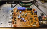
  8. What the circuit or schematic in the right of the image below is?
    1. I know it performs power conditioning but I don't have a reference in the manual for what the part values should be
    2. though I guess I could assume it has never been touched and just evaluate them in place
    3. I genuinely have never seen the part coming off the red-brown lines that is encased in glass lower right
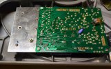
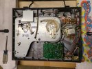
20250103_173209.google.pixel_8a.img_20250103_173208_945.jpg20250103_174306.google.pixel_8a.img_20250103_174305_789.jpg20250106_154356.google.pixel_8a.img_20250106_154356_365.jpg

Starting Restore Content Hints
  1. supporting upside down unit
    1. The manual says you can support on the dust cover, but it is both old and unobtainable now so much safer to do that (others say it breaks)
    2. remove dust cover
    3. Remove cartridge (just because)
    4. Remove rotating platter, pull up (I taped down paper to provide extra magnetic material shield)
    5. Make a negative of the dust cover on paper taped to a sturdy board. Scrap MDF works well.
    6. Then clamp a stack of support boards wrapped in cloth within 1/4 inch of the left and right edge dust cover outline using a carpenters square to check (see image)
      1. you need about 2 inches to clear the arm
      2. used 2x4 and 1x5 or 6
      3. wrapping in cloth holds the boards together and protects the turntable base from scratches
    7. The boards will catch the turntable base but not hit switches, controls, etc.
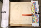
    8. 20250103_170546.google.pixel_8a.img_20250103_170546_321.jpg
  2. to remove the bottom you must remove all the red arrow marked screws
    1. the 5 long screws in the center
    2. 6 outer short screws
    3. the bottom cover just pops off after that
    4. you don't remove the feet cause they are mounted from the inside
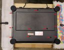
    5. 20250103_170823.google.pixel_8a.img_20250103_170822_974.jpg
  3. The circuit board is not soldered in
    1. remove 3 screws
    2. pull off lower right connector
    3. the board is shown flipped over, above, you can see the long pins that connect to the motor connector
 
Last edited:
Register to hide this ad
Answering my own questions ...
Q1: support while running -- same as support while upside down. to measure I'll need to make longer legs so more stable
Q5: decaying PVC "insulation" tubing is likely causing the odor as it warms it off gasses more. I cut the tubing off the power entry board, there is no metal on the bottom of the case to allow arcing. I think unnecessary but just in case I put electrical tape on the body support reference pin below the resistor and the solder tab below the fuse. Odor seems reduced but need more testing to confirm.
Q8.3 - that part is the strobe light for the speed setting circuit

The family is discussing whether to bother with a recap given the odor seems to be just off-gassing PVC and not imminent failure.

I did start to measure part sizes and look them up but may curtail that effort and just button it up for other projects. Will still push the research I did do to a git.
 
In my experience, Technics products (and many other brands too, such as HarmanKardon) of this vintage are chock full of those purpleish colored Matsushita aluminum electrolytic capacitors. This makes perfect sense because Technics is a subsidiary of Matsushita, so of course they would use their corporate family parts. The downside of this is that those caps are notorious for leaking electrolyte down the legs, where they will leave a powderey corrosion on one or both legs. Left long enough, this corrosion will eventually work its way down the legs to the circuit board where it will attack the solder and copper traces, chemically changing them. I've seen solder blobs turned into a dull grayish paste that simply falls apart, and copper traces that have turned black and lost all ability to conduct. This corrosion is like a cancer. It will not stop until it is removed and cleaned. Worst cases require jumper wires to restore the electrical connections. This only affects aluminum electrolytic capacitors. Film capacitors are almost always fine and no need to replace them unless bad (drifting out of tolerance, leaking DC, or shorted).

So take a close look at the legs of those elcos and inspect for any corrosion. If a cap is flush mounted to the board and you can't see the legs, check the trace side. If you see any burned looking discoloration of the board or black traces or bubbling or distorted flux covering that looks different than everywhere else, there's a good chance that cap is leaking and should be replaced.

The vinyl tubing can be cleaned with alcohol to like new again.
 
@nakmandan your post on "notorious for leaking electrolyte" push me over the small edge to just order parts.

Question
Anybody know why C4 marked as 1 uF on circuit and schematic in the manual was actually a 2.2 uF?
  • It is in parallel with R5 (3.9 kOhm) at the emitter of the switch controlling the transformer that connects to one of the motor winding sides.
  • I suspect switching 2.2 to 1 uF, which shifts the filter from 116 Hz to 256 Hz, really only allows faster switching action which may be less stable in some scenarios
  • It is being driven off point A which is AC power, 60 Hz, so it will let in more higher fundamentals of the power signal

What I did
  • I replaced all the electrolytic capacitors.
  • Replaced resistor R40 serial connected to C20 glued and connected inside PVC
  • Cleaned off the glue: mostly lightly scrapped because non-acetone nail polish remover did not soften much, maybe because it is very cold outside today.
  • used deoxit on the potentiometers
  • wiped down clear PVC with alcohol
  • Removed PVC from parts on circuit boards, then just in case lined the board below with electrical tape (likely unnecessary), so that the parts that are heating will stop causing the decaying PVC to off gas. The parts are not near anything that will short on the chassis as the bottom is plastic.
Outcome
Works no better or worse than before but now I don't need to worry about the electrolytic corrosion, and the turntable does not seem to smell during operation.
 
Parts that appear in products that differ from the schematic and parts list are usually factory mods done during the production run. The factory often did not put out amended service manuals or bulletins about these. So unless the suspect part you find has an amateurish look to it, maybe poor solder technique or a part that doesn't seem to match the style of other parts, or just an extremely poor addition, it is usually that way from the factory and can be left alone or replaced with a like part. This happens all the time in consumer products and I wouldn't lose any sleep over it.
 
Parts that appear in products that differ from the schematic and parts list are usually factory mods done during the production run. The factory often did not put out amended service manuals or bulletins about these. So unless the suspect part you find has an amateurish look to it, maybe poor solder technique or a part that doesn't seem to match the style of other parts, or just an extremely poor addition, it is usually that way from the factory and can be left alone or replaced with a like part. This happens all the time in consumer products and I wouldn't lose any sleep over it.
Undocumented factory mod is what I'd assumed ... I'm more curious if I care given I ordered the "wrong" part based on the documentation. IE the why of the change.
I do appreciate the response confirming assumption, just looking to absolve minor concerns so I can close it up and giving it back to the family member I'm fixing it for.
 
The other fact that lends reassurance for unexpected part changes is if you know the unit has been working properly for years or even decades as found.
 
The other fact that lends reassurance for unexpected part changes is if you know the unit has been working properly for years or even decades as found.
I found a new 2.2 uF Rubycon 50 v in the parts bin at the maker space I belong to which measures good. This avoids a single part order, or having to wait and reopen the unit later.
 
Last edited:
Back
Top Bottom