• The move to the new server is done. There are some software and database maintenance updates in process. This has us passing the hat around to help out. We appreciate any donations. Seriously, even a dollar helps. The payment page may be found here - https://www.audiokarma.org/support.html

Technics SL-1411, need some help

ZoKtorR

New Member
Hi,

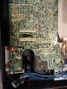
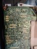
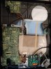
I have a Technics SL-1411 which doesn't spin but goes back and forth when I hit the start button:


I have an identical, working model, so through swapping parts I've determined that it's not in the start/stop board, nor in the motor.

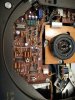
I've been replacing transistors on the control board, following the service manual but it doesn't make a lot of sense. I keep ketting the wrong voltages everywhere.

The funny thing is that it didn't have this fault when I got it. There was a fault in the start/stop board, but while fixing that, this new fault started. The start/stop board is not the same any more, I swapped it out with a working one, so the fault is not in there.

Does anyone have any idea/experience to help me with this? I've been struggling with this table for quite some time now.
 

Attachments

  • IMG_20210215_134523.jpg
    IMG_20210215_134523.jpg
    160.2 KB · Views: 12
  • IMG_20210215_134638.jpg
    IMG_20210215_134638.jpg
    177.9 KB · Views: 11
  • IMG_20210215_134646.jpg
    IMG_20210215_134646.jpg
    188.2 KB · Views: 11
  • IMG_20210215_134703.jpg
    IMG_20210215_134703.jpg
    153 KB · Views: 12
Register to hide this ad
Are you sure you've swapped for the equivalent transistors with the correct pinout? Are the old ones any good so you can revert - just in case? Initially, I'd suspect the electronic break (VR202) adjustment but now there's too many variables. You're gonna have to get way more specific with the voltages. I'd start with the power supply voltages and work upstream with the SM after following all the adjustment routines.
 
Last edited:
I swapped them correctly, I know this because at first I didn't do it correctly :) Checked the pinouts and corrected. No change. I'll provide the voltages.
 
I meant you're gonna have to be specific with voltages in the way you tackle this. I gave you a lead. I'm sorry I can't debug this from my desk. I don't think anyone can. It's too complex, you've complicated it even more, it will take ages to do online and it will not end well.
 
Alright, I misunderstood. I don't expect people to resolve it for me, I'm just looking for clues from people that have seen this before on this deck or similar.

To be clear: the problems arose before I started swapping transistors in the control/drive board. I'm swapping them because I want to find the cure. So far the symptoms have been exactly the same before and after the swaps.
 
The thirst thing to do would be to look at the waveforms at the motor driver transistors with a scope - it looks like you're missing a phase.
 
I've been replacing pretty much every electrolytic cap and every transistor on the board, and no change. Two caps were starting to leak though, so it was good to do it anyway. I'm beginning to suspect that there's either a faulty diode somewhere or a faulty IC. People say that IC's don't generally fail but I'm not going to assume.

I'll diagnose by swapping out bits with my working SL-1411 and see what changes.
 
If you have a working unit, I would not swap parts between the two. You run the risk of ending up with two non-functioning units.

Instead, I would compare voltages and waveforms between the working one and non-working one. As already stated, the first thing to check and correct is power supply. It must provide the rated voltage as per the schematic and minimum ripple. From the video you posted, it really gives the indication of one of the phases being wrong.
 
Also check that the signal from the drive transistors is actually getting to the motor - this means checking all the traces, wiring looms and solder joints very carefully.
 
Hi SaSi,
Thanks, will do. I'm not sure though what the voltage should be, directly from the transformer. Then behind the power transistors, I'm getting 13V, which is a little high compared to the standard 12V. I'll check the motor waveforms again and compare, but they all looked pretty clean.

Hi strato,
Thanks, will do :)
 
The motor is a three phase one (IIRC) and the video shows drive current irregularities. Either a phase is missing, or the phase angle is incorrect or the drive voltage is unstable.
To make the motor go in reverse while going forward, the sequence of sine wave drive voltages must become crooked.
It is conceivable that the problem is in the drive IC but it could be as simple as a broken trace or a cold solder joint.
 
Hi, I just discovered this old thread which takes me back two and a half years, to when I had this issue with my SL-1401.
So if you are still looking for clues perhaps my experience described in " Vinylengine" SL-1401 Quartz TT with oscillating platter can help. As I wrote in there it appeared that the quartz crystal was the cause.
I hope you get it going, they are nice decks.
 
Back
Top Bottom