
• The move to the new server is done. There are some software and database maintenance updates in process. This has us passing the hat around to help out. We appreciate any donations. Seriously, even a dollar helps. The payment page may be found here - https://www.audiokarma.org/support.html

Technics SU-8044 STK0039 issue 55V???

pirogoner

New Member
Hello, I'm trying to repair a Technics SU-8044 amplifier.
The last owner changed the LEFT STK because the left channel wasn't working.
After that it still doesn't work.

I dismounted both STK to test them but I don't know how to test them properly with a multimeter.
I joined the schematic.
stk0039-stk0059.jpg


Result of my testing on the unmounted STKs, multi-meter on "bip" mode.

OL means "1" is on the screen nothing happen, no bip.

First number is +(red) second is COM (black) :
RIGHT :
1->2 : OL
1->3 : OL
2->3 : 661
2->1 : 1135
3->1 : 1900 quickly, then OL
3->2 : OL
8->9 : 625
8->0 : OL
9->0 : OL
9->8 : OL
0->8 : 1135
0->9 : 802

LEFT :
1->2 : OL
1->3 : OL
2->3 : OL
2->1 : 796
3->1 : OL
3->2 : OL
8->9 : OL
8->0 : OL
9->0 : 366
9->8 : OL
0->8 : OL
0->9 : 366

Also, I tested the voltage on the "motherboard" without the STK, between pin 2 and 3 emplacements, which seems to be the input voltage of STKs. Here is the values I got :

Pin 2&3 LEFT STK = 33v
Pin 2&3 RIGHT STK = 55v

The schematics if I read it well tells me 39v on pin 2...
Schematic of SU-8044 is available here : https://elektrotanya.com/technics_su-8044_schematic.pdf/download.html

I dont get it.

I ordered a new STK0039 to replace the bad one, but I dont want to burn it if there is a problem somewhere else.

Also I cant remember what channel was working when I plugged in at first, sorry for that...

So my questions are :
1- How can I test a STK0039 with a multi-meter (If you could explain it very basic :/)
2- Is it normal to mesure 33v LEFT and 55v RIGHT ?
3- Is there some other measurement/testing I can/should do before replacing the STK?

Thank you in advance!
 

Attachments
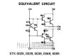
  • stk0039-stk0059.jpg
    stk0039-stk0059.jpg
    16.7 KB · Views: 17
Last edited:
Register to hide this ad
When testing channel without stk, you need to put two resistors to supply feedback routes, or output just goes to one of the rails...On the channel without the STK, use 220 ohm resistors between pin locations 0 to 8, and 1 to 3. And no load.
 
Thanks for your answers

I wouldn't think so..
I should place the red on pin 2 emplacement and the black on any mass to mesure pin2 voltage?
Thank you for the welcome :)

powered up voltages would be easier to diagnose .
You mean power up the amplifier with STKs in place and mesure voltage on STKs?

When testing channel without stk, you need to put two resistors to supply feedback routes, or output just goes to one of the rails...On the channel without the STK, use 220 ohm resistors between pin locations 0 to 8, and 1 to 3. And no load.
I removed both STKs so I should place 220ohms resistors on both STK locations? By testing you mean using a function generator(I don't have one :/)
 
By testing you mean using a function generator(I don't have one :/)
That would be better, but just measuring voltages to verify rest of circuit is the main point. If all ok, gets rid of the +35 on pins (and 8?) you were measuring earlier with the STK modules removed.
 
That would be better, but just measuring voltages to verify rest of circuit is the main point. If all ok, gets rid of the +35 on pins (and 8?) you were measuring earlier with the STK modules removed.
For testing without STKs, should I place 220ohms resistors (0-8 & 1-3) on both STK locations?
Just to be sure, I place the black electrode on any ground pin and with the red electrode I verify each voltage point of the circuit and compare it with voltage written in the datasheet?
 
For testing without STKs, should I place 220ohms resistors (0-8 & 1-3) on both STK locations?
Just to be sure, I place the black electrode on any ground pin and with the red electrode I verify each voltage point of the circuit and compare it with voltage written in the datasheet?
Use the resistors when you take an STK out. If you take one out, only use them on that side. If you take both, then you need them in both channels.
The pin 0 and pin 1 voltages will be a little off, but the rest of the circuit should work fine if everything ok, and if something bad, you can trouble shoot without worrying about taking out an STK.
 
Thank you, huge help!
Just to be sure, I put 220 ohm resistors, plug the amplifier, then with the voltmeter I place the black electrode on any ground pin and with the red electrode I verify each voltage point of the circuit and compare it with voltage written in the datasheet; is that correct ?
--> I don't want to ruin it when testing....
 
Thank you, huge help!
Just to be sure, I put 220 ohm resistors, plug the amplifier, then with the voltmeter I place the black electrode on any ground pin and with the red electrode I verify each voltage point of the circuit and compare it with voltage written in the datasheet; is that correct ?
--> I don't want to ruin it when testing....
That's correct.
Also a tip - put a piece of tape or insulator on the test leads, so only the tip is bare. Reduces significantly chances or shorting something out.
 
Pluging in the amplifier was very stressful :D .
I have the right voltage on every STK pins :beerchug: (with 220ohms resistors in place) so I can safely replace the STK and see if it was only a "fake chinese STK" problem.

Thank you again for the huge help!

Based on the measurement I made on both STKs, can you recognize the broken one?

If not, can I test STKs (when dismounted) with a Voltmeter?

Thx!
 
Build a "dim bulb tester" basically, an incandescent lamp in series with the AC. Limits the power if something is wrong. Bulb should be 60 to 100 watts. Must be incandescent. Will brighten briefly then end up with a glow but not bright if everything is ok. Search DBT or dim bulb tester for different people's realizations. Probably in DIY threads, but are elsewhere.

STKs are hard to test with a dmm. If you have a known good one, gives you some measurements to reference to. Two issues are that where there are more than one junction, most DMMs don't generate enough voltage to get a good measurement. Second issue is that schematic is "equivalent circuit" so there may be other components and resistance values aren't given. Neither one is what I expected from the equivalent diagram. Usually, bad original read low or shorted from 2 to 3 or from 8 to 0. Also, the 0039 STK are not symmetrical, so that can't be used to help trouble shoot.

The only measurement which definitely looks wrong to me is the 366 between pins 0 and 9 on the second STK.
 
Alright I'll receive a "good" STK shortly, and will try to test other STKs based on this one. I'll keep you updated, hopefully I'll succeed! Thanks!
 
I replaced the left STK, the amplifier is working like a charm! The seller probably bought a fake Chinese STK, I'm not complaining about it I bought the amplifier for 20€ and STK for 8€ :). Thank you again for your precious help!
 
Back
Top Bottom