• The move to the new server is done. There are some software and database maintenance updates in process. This has us passing the hat around to help out. We appreciate any donations. Seriously, even a dollar helps. The payment page may be found here - https://www.audiokarma.org/support.html

Technics SU-8088 with broken circuit board

karma_

New Member
Hi all,

I bought a Technics SU-8088, which is working, although one of the circuit board is broken (I assume it happened due to shaking, proper of international transportation).

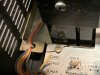
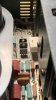
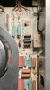
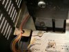
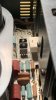
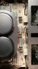
As seen in attached pictures, the circuit board of the main filler caps is broken nearby two of the screws, which I assume also support it’s weight. Apparently, it is not affecting any circuit.

Is the weight of the caps supported only by those screws, and is the rest of the board in stress?

What do you recommend I should do? Leave it has is, and enjoy until something worse happens?

Is there any possible fix, for instance glueing the circuit board? will I need another circuit board (because the rest of the amp looks good), and if so, is it replaceable with other models (for instance, the SU-8080)?
 

Attachments

  • 21CD3F66-D791-40EE-98F3-CF4B7870CF65.jpeg
    21CD3F66-D791-40EE-98F3-CF4B7870CF65.jpeg
    157.4 KB · Views: 47
  • 81D2A5D7-68E7-48CB-86C2-2F74DF91D1B8.jpeg
    81D2A5D7-68E7-48CB-86C2-2F74DF91D1B8.jpeg
    89.3 KB · Views: 43
Register to hide this ad
I can't tell from the picture, but it looks like it avoided any traces. You could flip it over to look at the bottom of the pcb to see if any traces were damaged. Likely the only thing that could be broken here would be if that screw were used as a ground point, but since there is no metal contact for the screw it doesn't look like it.

It's best to keep stress off the board in any case because it could break somewhere else and actually interrupt some traces. Not sure what the best solution would be to secure the board here, since you don't want to permanently secure the board down. If there is no trace here you could simply try to epoxy it together, keeping the hole for the screw open.
 
+1 on a good quality two part epoxy. You may need to get the board out and do the repair unstressed and then replace it once fully dry. I was able to do this same type of repair on a JVC pre with a same exact issue. It holds tightly to this day, some five years later
 
As long as there are no traces damaged or broken it should be fine to use but I would put it somewhere so it will never get moved or never need to move it ever again.

What you see with that broken board is the result of poor packing when shipping or also just being dropped accidentally when installing or moving about the house.

I dropped a boom box years ago only 1 foot above the ground and it seemed to hit a corner just right and cracked the entire circuit board about two inches across and I needed to resolder 40 cracks or so to get it working again.
 
If no traces have been damaged I'd glue the pieces back on, then after it's dry I'd support the under side of the board with something like a pre-drilled popsicle stick as long as the contact points aren't grounding points for the board.
 
Thank you all for your replies. I feel better now, knowing that it should be good for some more listening time.

It’s in a steady shelf. I only took it out twice, very carefully despite its heavy weight, to inspect the interior. Found a pair of bad capacitors (I presume, since they’re linked by a brown stain, in the middle of the capacitor height), in a circuit board right behind the speaker selector. To reach it, I will have to dismantle the circuit board to the right of the transformer, in the picture, since the bad caps are in a board underneath. When I get time to endeavor in such cap replacement, I’ll try to epoxy the board.

I guess this will always be a risk when ordering things from too far away… I always prefer to pick my buyings personally, but the only amp I found locally had 90% of the caps replaced, and that didn’t sound right to me. This one I bought was never inspected, and even came with the original manuals and guarantee certificates (!).

Packaging was good, with the amplifier surrounded by lots of sheets of plastic bubbles, which were then surrounded by folded pieces of cardboard. The outer package was surrounded with tape stating “fragile”, and was not visibly damaged or bent.
 
Thank you all for your replies. I feel better now, knowing that it should be good for some more listening time.

It’s in a steady shelf. I only took it out twice, very carefully despite its heavy weight, to inspect the interior. Found a pair of bad capacitors (I presume, since they’re linked by a brown stain, in the middle of the capacitor height), in a circuit board right behind the speaker selector. To reach it, I will have to dismantle the circuit board to the right of the transformer, in the picture, since the bad caps are in a board underneath. When I get time to endeavor in such cap replacement, I’ll try to epoxy the board.

I guess this will always be a risk when ordering things from too far away… I always prefer to pick my buyings personally, but the only amp I found locally had 90% of the caps replaced, and that didn’t sound right to me. This one I bought was never inspected, and even came with the original manuals and guarantee certificates (!).

Packaging was good, with the amplifier surrounded by lots of sheets of plastic bubbles, which were then surrounded by folded pieces of cardboard. The outer package was surrounded with tape stating “fragile”, and was not visibly damaged or bent.

If you have access to a multimeter measure the capacitance of those caps to be sure. Lots of times they were glued down and the glue can darken with age, but the caps are otherwise just fine.
 
That is new to me; I keep on learning about caps, but didn’t know they could be glued together. Thank you for the heads up.

According to the manual, the circuit board of those caps is the “meter circuit”, which I assume controls the VU/FL power meters.

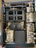
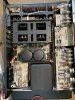
Here I attach better pictures of the broken board.

It seems that the board extends to the main power transistors (those that warm up), and may be further secured there, from the pictures in this other thread:
https://audiokarma.org/forums/index.php?threads/technics-su-8088-satisfactory-rebuild.608272/

As such, to remove the board, I assume I would have to unsolder the connections to such transistors, at the end of the broken board, and underneath the transistors. On the opposite side (towards the power transformer), I only see wires to unsolder, which seem easier to dismantle.
 

Attachments

  • 0905BF7A-6D8A-4D82-B1AA-826A51CFF2BE.jpeg
    0905BF7A-6D8A-4D82-B1AA-826A51CFF2BE.jpeg
    108.3 KB · Views: 12
  • 1DBFF538-E040-416C-B6CD-58D58C6E95F9.jpeg
    1DBFF538-E040-416C-B6CD-58D58C6E95F9.jpeg
    72.9 KB · Views: 12
  • 6922168C-CB94-458D-B94F-299E21240F04.jpeg
    6922168C-CB94-458D-B94F-299E21240F04.jpeg
    97.9 KB · Views: 12
  • 4D75A555-09AD-47D7-B7E5-F975DB87AF84.jpeg
    4D75A555-09AD-47D7-B7E5-F975DB87AF84.jpeg
    88.9 KB · Views: 12
EDIT: these are still not full resolution (it should be 2000x4000, not 500x900), but I don't know how to upload full resolution. I also don't know how to delete this post, since it has the same pictures as posted before.

Sorry for the repetition, but I’ve been posting resampled pictures. Here are with full resolution.

593A1833-872E-4128-A8A8-5ED3D9882D3C.jpeg E4980B79-0C41-47AC-AC3C-FD296BF52395.jpeg A2AB42E7-CD7C-4F30-A075-D3574FD93D60.jpeg 9F644D62-77FE-4704-9026-D8767F26569F.jpeg AA6262C0-D2A3-4FE4-8532-8A89E3FB4A58.jpeg
 
Last edited:
That is new to me; I keep on learning about caps, but didn’t know they could be glued together. Thank you for the heads up.

According to the manual, the circuit board of those caps is the “meter circuit”, which I assume controls the VU/FL power meters.

Here I attach better pictures of the broken board.

It seems that the board extends to the main power transistors (those that warm up), and may be further secured there, from the pictures in this other thread:
https://audiokarma.org/forums/index.php?threads/technics-su-8088-satisfactory-rebuild.608272/

As such, to remove the board, I assume I would have to unsolder the connections to such transistors, at the end of the broken board, and underneath the transistors. On the opposite side (towards the power transformer), I only see wires to unsolder, which seem easier to dismantle.

Not sure which cap you're pointing to in those pictures. I do however see another crack in the board around the other screw mounting there. Doesn't look like it impacts any traces, but you may want to address that one as well.
 
I was not able to capture the mentioned cap, as it was too hidden to get a clear shot, and it’s not shown in the pictures from the other thread.

I counted 2 cracks on this board, both near screws.
 
Last edited:
Can you recommend a particular epoxy glue? I've seen various, all in the form of a syringe with 2 merged tubes (that come out in a 1:1 ratio), from brands such as Loctite, UHU and JB Weld, but none mentions circuit boards.

UHU seems to be for metal only:
https://www.conrad.com/p/uhu-flussigmetall-two-component-adhesive-45960-24-ml-478805

the other two, seem to be for everything:
https://www.henkel-adhesives.com/pt/pt/produto/encapsulants/loctite_ea_3450.html
https://www.jbweld.com/product/clearweld-syringe
 
Back
Top Bottom