• The move to the new server is done. There are some software and database maintenance updates in process. This has us passing the hat around to help out. We appreciate any donations. Seriously, even a dollar helps. The payment page may be found here - https://www.audiokarma.org/support.html

Technics SU-V1X - No sound, Voltage on speaker terminal

Janochytron

Active Member
Hi,

I am new here and also to the world of amps. Only recently got a JVC ja s11 by dumb luck and love the sound it produces. Obviously I started to look at other amps and delas on ebay and got few more. I am interested in learning audio repair, so I got a faulty Technics SU-V1X for few bucks.

It has no sound out just loud hum and there is DC Voltage on speaker terminals. I have measured the pins on the IC - SVI 2003 A, new class A chip. The pins 3 and 14 should have 0 V, but have 33-34. Other supposedly low voltage outputs are all high, the high ones are slightly lower than in the schematic.

I can post measurements and correct voltages.
Similar on the other IC - AN7062 voltage amp.
Anyway, my question is, how can I make sure the ICs is faulty, what other measurements should I take?

When I opened the amp (very dirty, nicotin film all over the inside) I noticed a burnt circle on the upper cover (from inside) Under it I can see evidence of some burn around D505, 506,507,508 and resistors R501,502.

The voltages before and after look ok, all the diodes tested 0.943 on diode test (one way).

Any help would be greatly appreciated.

Pictures attached
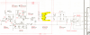
 

Attachments

  • SU v1X burn diodes.PNG
    SU v1X burn diodes.PNG
    235.8 KB · Views: 43
  • SU v1X ICs.PNG
    SU v1X ICs.PNG
    368.6 KB · Views: 38
Register to hide this ad
The diode/resistor and IC problems are probably related. Major current draw on power supply for power amp, maybe due
to speaker short. Diodes, resistors and IC's are toast. Diodes, resistors replaced in hope. Can't say for sure about the IC.
Pix are only moderate resolution and eyesight is not good enough. Couldn't find the service manual, maybe upload into
AK database if you have one. Difficult to get support without SM or SM of similiar model.
 
You're lucky that SVI2004A has joined your thread, this is his area of expertise.

From my own personal recent experience with a chip amp system, I can say that it is pretty unlikely the IC will be bad. I had a problem very like yours where I had bad hum through speakers and large amounts of DC coming through the outputs ( over 30v).

I replace the capacitors in the power amp and a suspect fusible resistor and afterward the DC and hum were gone. I would pay attention to any capacitors in the signal path, where they would be used to block DC but allow the AC to pass on through. If those caps have failed, that will give the problem you describe.
 
Possibly could be C307, C308, C309, C310. I see those in the signal path from the tone amp to the power amp.
 
Thanks for your interest, really much appreciated. I hope you are correct and the issue is not the ICs. I will check those when I get home.
 
You are very welcome, I'm very much a beginner at board level repairs myself but I have completed a few successfully recently.

I have found in all cases, ICs were never bad. Caps, transistors, resistors, diodes, micro switches, relays, solder joints, earth points, all of those cause problems but so far not one IC has been bad.

What voltages do you read on the inputs to IC301 (tone amp) ? Check pins 2,3, 5 and 6 because they should all be zero DC. Likewise the outputs 1 and 7 should be at zero too.

If there's DC going into the tone amp, its going to go all through the rest of the amp circuit. C301 and C302 are the filter caps for input into the tone amp so they could be suspect.
 
Last edited:
Let's see if I just broke one....
The voltage on collectors of q401 and q 402 was 35.7V on both. That was until I went to measure the IC again and the probe slipped and a little spark went off.
Now q402 reads 37.2V and q401 reads 22.3V.

For the capacitors. I don't have a solder gun yet, so can't take them out of circuit. Just tested for continuity, one of them gave a short beep, but stopped. I actually have those values caps so I might just replace them (when the solder station arrives).

Thanks again.

Petr
 
Is voltage on Left channel near 22v point now?

It's not likely the SVI as output voltages are near on collector voltages of 401 Lch and 402 Rch.

Now let's look at power supply feeds to AN7062 and collector voltage at Q505 (this feeds mute circuit of AN7062 and applies voltage to resistor pulldown to SVI (current stabiliser))

An7062 pin 9 +Rail voltage.... pin 10 -15V
 
Hi, left speaker was 20V, but went down to 18V on second measurement and 16.6V on third...

collector of Q505 is 24.2V

Pin 9 of An7062 is 44.6V
Pin 10 -15.4V

Thanks
 
It to start with will be a process of going through the power mute circuitry

*There should be a lot more voltage at collector on Q505, lack voltage there and it can drift into +V offset.

** Once there is -Rail voltage (40-47V depending if on 4 or 8 ohm setting) then we can get a better sense of balance. Then we will look into each channel more so (also to check if the short on Q401 has upset the AN7062)

Check voltages starting from Q505 and work back to rectifier diodes on that circuit, compare with the manual, somewhere lies the reason.
do check thoroughly, it could be an open resistor or diode behind this let alone transistors.
 
Hi,

thanks for your reply. Pardon my ignorance. Just to clarify:

"Check voltages starting from Q505 and work back to rectifier diodes" - so from Q505 to D509 /D512 ?

Below is what I measured where Voltages are stated on the schematics: first number from schematics, second my measurement

the q505 today reads negative, quite close to what it should be (now I am not sure if I just measured something else yesterday, they all look the same!!:-)

The voltages on the speaker terminals are 11V on left and 35V on the right. Seem to be different every day.

Do I have to just test all the components in this circuit or can I (or you in this case) narrow it down to a section from the measurements?

q505 Collector -47.2 -44.8
Base -46.7 -44.2
Emitter -47.2 -44.9

q504 Collector -20.9 -20.8
Base 0 0.1
Emitter 0.6 0.7

q503 Collector -15.2 -14.6
Base 0.6 0.5
Emitter 0.6 0.5

q502 Collector 0.6 0.5
Base -15.2 -14.6
Emitter -15.2 -14.8

q501 Collector 0 0
Base 0.6 0.5
Emitter 0 0
 
Those voltages look pretty good , I think. Not far off what the manual states.

Does the hum change with the volume control, or is it constant ? I'm guessing it will be constant. If it were me, I'd be swapping out those filter caps. Its easy to do, they're probably off-spec anyway, and it might resolve your problem :)

Good luck !
 
OK, so I measured further on the tone control circuit.

On the IC301, pins 8 and 4 measure as they should (around 15.8 +/-), but all other pins measured high voltages where there should be 0.

The pins on the cable with 5 wires to the board measures 15.8 +/- on pins for and five, but then also has high voltages on remaining 3 pins

I will replace the caps and test other components on the tone board (when I get my soldering iron:-)

Thanks for your support!
 
Hi, finally I got the this thing again. I have changed all electrolytic caps (except for the two 6800 UF and phono preamp's) juts to eliminate the possibility of caps being the issue (I was planning a recap anyway).
The thing is, that both before the recap and now after, the voltage on Collector of q505 is sometimes negative 46, sometimes positive. And looking further, the voltage of pin 18 of AN7062 which should be -10.8, it could be -10.8 (when q505 is aprox -46) but it could be positive 30 when q505 is positive and negative too. SO then I have positive voltage on one side of r424 and negative on the other....

Voltages from q505 to rectifier diodes are ok. I think that part is ok, the dc has to be filtering into the signal either in the ICs or somewhere in power amplifier section (I think)

AN7062 has the high voltages ok, the ones that should be close to 0 are high.

I tested resistors all around, they seem to be ok. Checked transistors q 401 and q402. Checked the diodes around the ICs, look ok. How can I eliminate the ICs being the culprits?

Un saludo

Petr
 
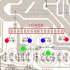
IMG_0142.JPG

SVI test points

RED is input
GREEN output
RED -Input (pulldown)

Pins 1,3,5 for Left Channel.
Pins 12,14,16 Right Channel

Check voltage between RED and BLUE should be approx 3.6v
Check output voltage (green)
Check input, this should be +1.8v approx higher than output
Check Blue this should be -1.8v on output

Example is of output is +35V input should be approx 36.8V and -input should be 33.2v

Can check between input (RED) and output (GREEN) should be 1.8v approx
Same for BLUE and GREEN - blue should be -1.8v

Approx value, this may change a little from bias.
 
Hi, thanks for replying so quickly.

So when the voltage on collector of q505 is around -44 (as it should be), the readings on svi are:

pin 1 39.9
pin 3 38.2
pin 5 36.2

so differences of 1.7 and -2

pin 12 23.9
pin 14 25.8
pin 16 27.5

differences of 1.9 and -1.7

The voltage between
c418 and c420 is 3.4V
and c417-c419 3.6V
and red to green 1.7 and 1.6.

So the differences look ok.

Sometimes though the voltage on collector of q505 is positive 45, then the IC voltages are all over the place.

Voltages on AN7062 (with coll q505 negative 44):

pin 17 29.5
pin 16 33.3
pin 11 43.9

pin 2 21.8
pin 3 25.4
pin 8 43.2
 
Back
Top Bottom