

Thank you in advance for reading - I have a Technics SU-V6 that I am recapping (some distortion in the right channel, no bass in the left channel, I have confirmed it is the unit causing the issue. It was purchased in 1981 by my parents, and so I expect the caps are bad (none have failed obviously).
I have some questions:
1. 8 (3 pairs and two single) capacitors I removed from the board differed from the values referenced in the service manual. Two of these substantially - which value would you use to replace them?
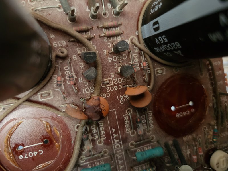
2. Any thoughts on the goop on the ceramic capacitor in the attached photo?
3. Would you have any concerns replacing the 8200uF/56V caps with 8200uF/63V caps? I think and it seems like google agrees that this should not create any problems; but I would like to back that up...
4. Disassembly has been a pain in the butt and my only testing equipment is a multimeter. What components would you consider replacing proactively?
5. Several of the switches and selection inputs have some problems (Deoxit fixed the pot-based inputs). Specifically the phono selector will sometimes cut the left channel entirely (these are the rotary switches with the metal bands attached). I am not sure how to even look these up. Any recommendations on cleaning these (tooth brush and deoxit?).
Thank you for any help - I browse the forum all the time, excited to actually participate.
I have some questions:
1. 8 (3 pairs and two single) capacitors I removed from the board differed from the values referenced in the service manual. Two of these substantially - which value would you use to replace them?
2. Any thoughts on the goop on the ceramic capacitor in the attached photo?
3. Would you have any concerns replacing the 8200uF/56V caps with 8200uF/63V caps? I think and it seems like google agrees that this should not create any problems; but I would like to back that up...
4. Disassembly has been a pain in the butt and my only testing equipment is a multimeter. What components would you consider replacing proactively?
5. Several of the switches and selection inputs have some problems (Deoxit fixed the pot-based inputs). Specifically the phono selector will sometimes cut the left channel entirely (these are the rotary switches with the metal bands attached). I am not sure how to even look these up. Any recommendations on cleaning these (tooth brush and deoxit?).
Thank you for any help - I browse the forum all the time, excited to actually participate.





 .. Two more screws and it sounds amazing! Thank you all for the help.