• The move to the new server is done. There are some software and database maintenance updates in process. This has us passing the hat around to help out. We appreciate any donations. Seriously, even a dollar helps. The payment page may be found here - https://www.audiokarma.org/support.html

Technics SU-V707 Help (Stuck in protection mode)

PreytorFenix

New Member
Hello all,

I recently got a hold of a 707 but can't seem to get it past the initial power on state.
upon pressing the power button, the standby light will flash slowly then after a few seconds it will begin to flash at a faster rate and will not do anything else until the unit is powered back off.
upon inspection of the internals everything looks fine and all fuses test out okay but I really don't have enough experience to know what else I can look for.

According to the manual the Protection mode is "to prevent circuitry damage if, for example, the positive and negative speaker connection wires are 'shorted'."
This is about as far as I have gotten but any tips or suggestions would be fantastic.
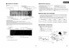
technics_su-v707_Page_14.jpg
 
Register to hide this ad
The 2 common scenarios are 1) a fault has occurred and the protection system is doing it's job, releaing the relay and isolating the speakers. 2) a fault has occurred in the protection circuit. From your symptoms, mopst likely 1).

To track down the fault you will need a multimeter and be comfortable taking measurements on a live amp (lethal voltages inside).
There are some tests that you can perform on a powered down unit. Do you have the tools/diy skills? Will look at service manual
to find some test points...
 
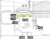
Measure dc voltage at TP301. Repeat for TP302, TP303, TP304 ap per pix. Black meter probe connected to chassis/ground.
Expect less than 100mV. You may have 1-57Vdc.

I'm testing for excessive dc voltage on the speaker lines, the test points are for checking/setting the bias and are "close enough"
to the speaker line and readily accessable.
 
. Do you have the tools/diy skills? Will look at service manual
to find some test points...
At the moment I don't but hopefully I should be able to find my multimeter tomorrow.

If it turns out the relay is the issue I found a seller in Germany who has them fairly cheap.
I'm still debating if the struggle is worth it.
I only paid $45 for the unit so it's not a big loss but I would love to be able to get it functional again.
 
Don't rush to buy any parts. Also don't buy parts off the "bay"
Protection faults can be tricky to sort out, depends how much spare time you have and if you want to learn diy...
if not then that's ok, sell it and cut your losses. Typically protection faults are caused by failed silicon, eg, output transistors
or others. The outputs will be heatsink mounted, maybe post a hi-res pic of the outputs and surrounding area, look for any
discoloured/charred resistors in the area. Will read up on amps protection circuitry...
 
Thanks a bunch for the help.
I was kinda at a loss.
I will return tomorrow with Pictures and hopefully some measurements.
 
After some brief probing I have found no voltage on TP301 & 302. 303 & 304 had about 10 or so mV but slowly drops over time. Cap discharging I guess?

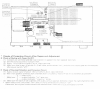
Here are a few pictures.
 
That's what I thought as well at first.
Unfortunately it was the same after it was powered on with speakers.

I was kinda thinking the opposite - if at first your powered up with speakers attached and they were faulty, that would throw you into protection. Removing the speakers would hopefully result in a successful power up.

Anyway, that's clearly not the issue for you. Have you followed steps 1, 2 and 3 for 'check of overload detection and protection circuit' ?
 
Oof.
I was hoping to avoid poking at the ic chips.
As for attempts at the check of overload stuff I don't have a signal gen on hand but could probably find one.
Is it really worth my time to get this thing runing or should I just sell for scrap and find another amp?
 
Orright let’s start on gathering a sense of what’s goin on in there...

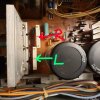
With meter - lead to ground and amplifier on, check for DC voltage from the centre pin of Emitter resistor Z301 (Lch) and then check Z302 (Rch)
D81C2A0B-338F-463E-8F01-57F1BA1F1424.jpeg
If these are near 0V power amp section should be ok and fault will be elsewhere (will go over protect circuits if need be)

I do recommend looking keenly for dry joints too...
 

That could be bias - and you could have mV between them... it’s reference to ground I’m looking into atm. And just making sure that’s clear... kinda gonna need long arms to test it from here lol
 
That could be bias - and you could have mV between them... it’s reference to ground I’m looking into atm. And just making sure that’s clear... kinda gonna need long arms to test it from here lol
Yeah currently at work but when I get off I should be able to check the center points.
 
Back
Top Bottom