• The move to the new server is done. There are some software and database maintenance updates in process. This has us passing the hat around to help out. We appreciate any donations. Seriously, even a dollar helps. The payment page may be found here - https://www.audiokarma.org/support.html

Technics SU-V85A amplifier restoration

leesonic

Captured on security camera...
Subscriber
I've been working on something a little different lately, a late 1980s Technics SU-V85A amplifier. Some people think that when I cut myself, I bleed NAD, but that's not true, I collect and work on equipment from all manufacturers. I sort of steer clear of amplifiers of this era though, as sometimes they have those SVI or STK output modules. I always wanted to restore a Technics SU-V4 (with the silver face and FL power meters), but the output modules put me off. Same thing with the Kenwood KA-8300. But looking at the topology of this SU-V85A, it's old school, in that it has a conventional pair of power transistors for the output, and an EI frame transformer with traditional rectifier and smoothing caps.

It still has some interesting circuitry though, with remote switching for all the inputs. It also has very few capacitors in the signal path, which is what attracted me to it. Finally, it appears to have something similar to what Quad used to do with their current dumping amps. There is a small higher quality voltage amplifier driving a more hefty current drive amplifier. Technics claim some low distortion figures for this design. You can read a review of it here :

http://www.hifi-review.com/153611-technics-su-v85a.html

index.php
 
Register to hide this ad
Most of the smaller boards are attached to the front panel. They are a bit fiddly to remove, but after a while I got it to look like this.

Technics SU-V85A 01.jpg

As with all of my projects, I always pull the output transistors off, and here is why. The heatsink grease, thermal paste, whatever you want to call it had all dried out. So much so, I had to get busy with some paper towel and rubbing alcohol to remove the old stuff from the heatsink, mica washers, and transistors.

Technics SU-V85A 02.jpg

Here is the main board recapped. I upgraded the main caps from 5600uF to 6800uF, this seemed like a useful upgrade without straining the single bridge rectifier too much.

Technics SU-V85A 03.jpg

Tone control board. Some WIMA films and Nichicon ES here.

Technics SU-V85A 04.jpg

Phono preamp board. I was just able to squeeze two 2200uF Nichicon KLs which form part of the signal path for the phono preamp in there.

Technics SU-V85A 05.jpg

This board has a weird 2.3F cap on, presumably for the electronic switching to remember what input was selected. I left this one on there.

Technics SU-V85A 06.jpg

Another view of the main board. 6800uF main caps, Bournes trimmers to adjust the voltage control and current drive idle current.

Technics SU-V85A 07.jpg

All finished, and somewhat back together. I left it running into some 4 ohm 6x9 car speakers with the loudness on and the bass all the way up, trying to get some heat into it. After about 30 minutes, the heatsink had just got mildly warm.

Technics SU-V85A 08.jpg

Lee.
 
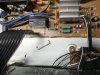
I had a problem with the volume pot for this amplifier. Even after numerous De-Oxit baths, the thing was still noisy. The back of the pot says M100K(ohm)B, that makes it linear. The specs of the pot are as follows. The hole size in the panel is 8mm. The terminals are 15mm apart from one end of the track to the other, so 7.5mm from the wiper to the end. They are also 10mm apart between the two gangs, like front wafer rear wafer. The shaft length is 25mm including the threads, 15mm excluding them, and the shaft is D-shaped.

Technics SU-V85A 09.jpg

Technics SU-V85A 10.jpg

I ordered four different pots from Mouser, all of them I knew would be too small physically. But when they arrived, they are WAY too small, some of them are even smaller than trimmers. I looked on Amazon, I looked on eBay. If I could get a fake Alps Blue pot with the same shaft configuration, I would have tried that, but I can't seem to find any. Then something made me think of RS Components in the UK. I found a pot there that while not totally 100% fit, I figured I could make work.

Technics SU-V85A 11.jpg

What I did was cut the shaft down, and file the flat on the shaft a little more, well, flat. Since the pins were solder lugs instead of PC pins, rather than try and make it work on the original circuit board, I removed the wires and soldered them directly to the pot. There were also two 56K resistors across the pot, so I just found some from my spares box. The original pot had a metal screen around it, so I soldered a ground wire to the new pots can.

Technics SU-V85A 12.jpg

Technics SU-V85A 13.jpg

The new pot had a different position of the D-shaft in relation to the position of the wipers. I just re-drilled the index hole to suit, enlarged the mounting hole to 3/8", and it fits just fine. Technics really take grounding seriously on this amp, there was a piece of aluminum foil that shields the front of the pot, I refitted this rotated to suit.

Technics SU-V85A 14.jpg

Now it plays just fine with no crackle from the volume control. :music::banana:
 
wonder if the pot was damaged from DC leakage from the old caps. I've had problems with that in the past. Sometimes changing the caps is enough to make it happy but if the damage is too severe a new part is the only practical solution.

I have a Kenwood preamp with a similar high value / low voltage cap in the memory circuit. Its got some odd markings on it if I remember but basically its super low leakage and acts as a battery.
 
I'm a Technics fan. But I do prefer the earlier units. I have no experience with any of their Class AA offerings. I had an SU-V4 but I gave that away instead of trying to fix it. It was replaced by an MCS 3842, which is also a Technics unit. I'm curious if you ever dug into that SU-V6 that I sent your way. I know you did one of those previously. Did the SU-V6 use discrete componenets or did it have modules as well? I didn't see anything on the service manual when I peeked... That SU-V6 was a beast at over 27 pounds. A bit much for me frankly. The SU-V707 I now have weighs less and sounds good. And has more power.

For late eighties that SU-V85A looks to be of good quality and it can deliver 100 WPC, at low distortion to boot. Says it can drive a 4 ohm load...
 
just got mine last week. the volume pot has scratch noise when start turning up or down closing to zero. No noise if I turn really slowly. should I try dexoit first? IMG_0007 (002).JPG
 
just got mine last week. the volume pot has scratch noise when start turning up or down closing to zero. No noise if I turn really slowly. should I try dexoit first? View attachment 2389508
Always a good place to start. I actually used a product called De-Ox-Id on a volume control on an SU-V707. But it doesn't really matter as long as you use something good and make sure that when you are done there is some sort of lubricant remaining in there.
 
@leesonic
"Here is the main board recapped. I upgraded the main caps from 5600uF to 6800uF, this seemed like a useful upgrade without straining the single bridge rectifier too much."
Would you mind sharing what capacitors you use for these?
The SM I downloaded seems different and only shows 2 71V/100000 capacitors, C601/C602?
 
There is a revision that uses 4 x 5600uF caps instead of 2 x 100000uF. I believe I used Cornell Dubilier.
 
IMG_7442 (002).JPG
How do you disconnect these white wire connector like J10 and J14?

@leesonic, I saw yours is different from mine, did you totally remove the connectors?
 
Last edited:
Push down the tab (side closer to the edge of the circuit board) and pull the ribbon cable gently. IF you are not able to push down, a little squirt of deoxit will help loosen it.
 
I actually pulled that cap off, oops.

IMG_7443 (002).jpg

But put it back and try your instruction and works and I assume insulation just insert the wire back in, or do I also need to push the tab at the same time? Thanks.

IMG_7444 (002).JPG
 
With mine, the wires going into that connector had bent over the years, so the wires wouldn't come out cleanly. After straightening the pins out two times, when I eventually put the amp back together, I soldered the wires directly to the board.
 
Still exploring this unit. Debating want to changing out the old capacitors or not? @leesonic, how much improvement you hear on your recapped unit? Just curious. On most of units I did, my untrained ears just can’t tell that much of difference. They all sounds nice to me.
 
Still exploring this unit. Debating want to changing out the old capacitors or not? @leesonic, how much improvement you hear on your recapped unit? Just curious. On most of units I did, my untrained ears just can’t tell that much of difference. They all sounds nice to me.

Hope this won't break the "zombie thread" rule, being almost 2 years on. In my defense, I came across this unanswered reply when looking for another Technics amplifier.

@EC1 in answer to your question, it sounded pretty good when I first got it. However, after recapping it, it seemed like a slight veil was lifted from the music. There is certainly no shortage of power with this amp, but swapping out the main caps to 4 x 6800uF seemed to tighten the bass a little. It could all be in the mind though...
 
I've been working on something a little different lately, a late 1980s Technics SU-V85A amplifier. Some people think that when I cut myself, I bleed NAD, but that's not true, I collect and work on equipment from all manufacturers. I sort of steer clear of amplifiers of this era though, as sometimes they have those SVI or STK output modules. I always wanted to restore a Technics SU-V4 (with the silver face and FL power meters), but the output modules put me off. Same thing with the Kenwood KA-8300. But looking at the topology of this SU-V85A, it's old school, in that it has a conventional pair of power transistors for the output, and an EI frame transformer with traditional rectifier and smoothing caps.

It still has some interesting circuitry though, with remote switching for all the inputs. It also has very few capacitors in the signal path, which is what attracted me to it. Finally, it appears to have something similar to what Quad used to do with their current dumping amps. There is a small higher quality voltage amplifier driving a more hefty current drive amplifier. Technics claim some low distortion figures for this design. You can read a review of it here :

http://www.hifi-review.com/153611-technics-su-v85a.html

index.php
I have the possibility to inherit one of these units, however there is a channel out. Do you have any idea of where I should start looking in relation to what the problem might be?
 
Hi guys can you guys help me with the voltages I'm having 96V in the transformer when in the service manual it should be 44V
 
Back
Top Bottom