• The move to the new server is done. There are some software and database maintenance updates in process. This has us passing the hat around to help out. We appreciate any donations. Seriously, even a dollar helps. The payment page may be found here - https://www.audiokarma.org/support.html

Technics SU-V9, and not following the golden rule

Ju@n

Member
Hi!
I bought a SU-V9 a couple months ago, when I got it, it looked as if it had spent it's life within a cigarette, literally. It was working but barely, controls were all dirty.
So, disassembled it completely, cleaned everything, controls, relays, etc.
After assembly it was working pretty good!

Now, I've been brainwashed about recapping, and have had my share of luck here, the last one I did, a SU-C01 and SE-C01 changed dramatically, and it goes along with the measurements of the caps that were in vs the ones that replaced them.
However, with this V9 it seems I did something wrong, or replaced some cap with a type I shouldn't have.

I replaced everything below 10uf with MK2S Wima caps, and everything above that with modern Panasonic or Nichicon equivalents.

The V9 now doesn't click now though :(

So, I'm trying to diagnose it before trying to change back caps in certain sections.

I've measured Voltage across the emitter resistors, both how it's indicated in the manual to adjust Icq and against chassis ground, and measurements are very close to 0v for all 4 measurements. My guess it's not a matter of the Amp part of the Amp being actually bad, but rather the Impedance detector.

But after this I'm at a loss since honestly this goes way above my head for diagnosing skills.

Thanks in advance for any instructions/ideas :)

Juan
 
Register to hide this ad
It may be an obvious answer, but if the amp was working before you installed new caps, it's likely you've either got a polarized cap installed backwards, a bad solder joint, or a solder bridge. Go over your work very carefully and check. If you had to disconnect any wires, or stressed any wiring, for access to the boards, check these as well.

As long as the values are correct, using a different type of capacitor than orginal (for example, film to replace electrolytic) will not cause a complete failure. Did you replace/remove any transistors?

I assume since you have been replacing components, you have a DBT. If so, does it indicate a short?

BTW, I though the Golden Rule was "treat others as you want to be treated"?
 
Last edited:
It may be an obvious answer, but if the amp was working before you installed new caps, it's likely you've either got a polarized cap installed backwards, a bad solder joint, or a solder bridge. Go over your work very carefully and check. If you had to disconnect any wires, or stressed any wiring, for access to the boards, check these as well.

As long as the values are correct, using a different type of capacitor than orginal (for example, film to replace electrolytic) will not cause a complete failure. Did you replace/remove any transistors?

I assume since you have been replacing components, you have a DBT. If so, does it indicate a short?

BTW, I though the Golden Rule was "treat others as you want to be treated"?
Thanks for the quick reply!
Makes perfect sense, I've been going over the job, mainly on what I suspect are the most probable culprits. For now I've found nothing too bad.
I've gotta recheck the values, just in case I fumbled something up, I've check polarity and it seems ok.
I've already checked wiring as well, as I initially thought I might have not connected some wire but no dice on that front :(

I did not remove any transistors this time, I did that for the power transistors back when I bought it to change the thermal paste, but it did work after that.
I do have a DBT and there's no short indicated :)

Another thing I noticed is that the board that contains the Impedance detector circuitry doesn't share the ground with the rest of the amp, the relay does click, measured voltage across both grounds when disconnected and it's close to 17v. Found this by mistake while testing other stuff.

Hahaha about the golden rule, I was thinking more along the lines of "if it works, don't fix it" lol!
 
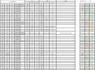
Btw, here's the table I've been doing when recapping equipment, I've still gotta check that all the caps are in the correct place, since I do replace 2-3 at the same time and I could have made a mistake. The values in red/green are percentage difference from what should be present.
Screenshot 2025-01-05 at 10.58.07 PM.png
 
Love this unit. Very underrated.

Check your work, and don’t feel bad, the two of these I’ve restored had caps with corroded leads that were eating through the board. It does need to be recapped.
 
Alright, I fudged up on a cap, placed it wrong way, amazing it didn't blow up!

Now the amp is working :), but I did notice some stuff that I could have missed before, since I never checked that the voltage changed for different impedances.

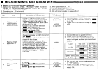
Apparently the procedure to adjust it involves first adjusting the impedance detector threshold.
Set up 2 3.3ohm 1/2 watts resistors in series for each channel on Main
Volume to minimum
Main speaker switch on, remote off
Straight DC

To do that it says to jump TP703 to chassis (did that).
Then measure between TP702 and adjust VR702 to set it to -0.1v, that worked perfectly, however, when I do the same to TP701/VR701 (measure between TP701 and chassis, adjust VR701 so that it's 0v) I can't get that low, it was at about 17v when I started, and the most I can get it down is 12.8v.
I noticed that bridging TP703 to ground has an effect (power cycles in the middle just in case haha) on TP702, but not on TP701.
Screenshot 2025-01-06 at 1.56.01 AM.png


Also I looked a bit at the schematic, and it makes sense that TP703 would affect TP702, but can't see how it works for TP701.Screenshot 2025-01-06 at 2.02.27 AM.png

Thanks in advance for any ideas!
 
Tested with 8ohm in remote, 6.6ohm in main.
Adjusted voltage (needed minimum adjustment), with 8ohm it's at 54-55v, with both 8ohm and 6.6ohm (so, 3.6ohm when both main and remote selected), it's at almost 46v.
Between Q327 collector and TP502 it's a tiny bit lower than between TP502 and TP503.
 
Recapping a direct coupled amp… wouldn’t be much to gain sonically
im a till a recap skeptic… see sooo many “it was perfectly fine till I recapped it“ threads
 
Alright, V9 working perfectly :)
Turned out one of the 6.6ohm resistors I'd been using to adjust these amps drifted to more than 10 ohms. Noticed that if I swapped them between sides, TP701 and TP702 would swap as well. The error was between the keyboard and the chair haha.
Adjusted everything according to manual
DC Offset is -.3 mv on the left channel and 2.5mv on the right. I don't think that's an issue :)
I left IcQ between 1.0mv and 1.1mv.

Thanks for the feedback !
 
Recapping a direct coupled amp… wouldn’t be much to gain sonically
im a till a recap skeptic… see sooo many “it was perfectly fine till I recapped it“ threads
I'd agree with you in general. I've recapped all my gear, and I only noticed differences on a couple amps and a tuner, although for those I must also say that I found some caps that were waaaaay off.

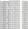
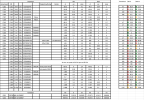
Here's an example :)

SU-C01 (values in red/yellow/green are absolute percentage difference from what the spec on the cap said)
Screenshot 2025-01-06 at 12.17.55 PM.png

SE-C01
Screenshot 2025-01-06 at 12.22.08 PM.png
 
the V9/909 I consider the best integrated for the vinyl enthusiast… quite the phono section these have… and those big SanKen outputs are sublime… hence they use 18,000uf caps in the power supply :)
 
Small question, probably idiotic, but nonetheless.

On other full width amps I have temp on the top of the case after some usage (low volume), is warm, but far from hot.
I've been testing the V9 since yesterday, and noticed the top is a tad hotter.
Measured it at ~ 45C/112F, this is on the top of the case, I suppose it's even hotter inside. Do those temps sound ok?

Thanks in advance!
 
A lot of new class A amps run warm…

what Is icq like?
usually I replace bias trimpots with sealed dustproof bourns pots to eliminate drift
 
I didn't replace trimpots to be honest, might do it just to forget about it. I did clean them.
icq is a bit less than 17mv (16.5mv and 16.3mv) after about an hour using the amp with 8ohm speakers. (Did change the input for measurement and lowered volume so it wouldn't affect)
 
Should all be good… quite a few of my amps run fairly warm at idle and made a lot of heat in operation… never had issues due to it
 
Back
Top Bottom