• The move to the new server is done. There are some software and database maintenance updates in process. This has us passing the hat around to help out. We appreciate any donations. Seriously, even a dollar helps. The payment page may be found here - https://www.audiokarma.org/support.html

Temporary red plating?????

rudedogg

AK Member
Subscriber
Hey all, i just picked up an old Allied 333 receiver. It looks great and sounds pretty nice. I ran it for about a half an hour this morning and it began losing stereo and also red plated the power tubes for about a minute and a half. The receiver had been running for about ten minutes before this.I fiddled with the controls and it quit red plating and regained stereo during that. I really have no idea if the controls had anything to do with stopping the red plating tubes tho. All four glowed for a minute or so. I felt the trannies and multicaps, they were cool to touch....what happened?
 
Register to hide this ad
Most likely the output tubes have lost negative bias due to either leaky coupling capacitors or loss of negative bias on the grids of the output tubes. I don't have the correct schematic but a similar one. The grid should be negative in relation to the cathode, possibly around -17 volts or so I think.

Just a guess...
 
Thanks for the response. The strange thing is that either two, or all four outputs redplated for a minute. I "wiggled" all the tubes into their sockets tighter, checked the hum pots, and gave everything a good look at least. Turned the receiver back on and cannot get the amp section to do this again...think i better have a tech check this one out and replace all the coupling caps at least!
 
Thanks for the response. The strange thing is that either two, or all four outputs redplated for a minute. I "wiggled" all the tubes into their sockets tighter, checked the hum pots, and gave everything a good look at least. Turned the receiver back on and cannot get the amp section to do this again...think i better have a tech check this one out and replace all the coupling caps at least!

Probably a good idea. :yes:
 
I don't have a schematic (as I had said above) so I can't comment on how the output tubes get their bias. They must have bias or will run away (red plate). Much of the time is caused by the coupling capacitor becoming electrically leaky and passing the DC voltage of the previous stage on to the grid of the output tube. Capacitors only couple the AC signal, not the DC.

The 333 is not a bad receiver. There were other variations of it and I think that it is also called a Pioneer 34X or something like that. Uses a triode/pentode output tube for about 10-12 watts per channel. Not too bad.

Please keep us up on your progress and of course, we love pictures!
 
I don't have a schematic (as I had said above) so I can't comment on how the output tubes get their bias. They must have bias or will run away (red plate). Much of the time is caused by the coupling capacitor becoming electrically leaky and passing the DC voltage of the previous stage on to the grid of the output tube. Capacitors only couple the AC signal, not the DC.

I see. Is it often that the power tubes could temporarily regain their bias? I have taken it out of service for now, but it ran again for quite awhile without incident. I will get her checked out of course. Do you think replacing coupling caps is something a novice like myself can do? I have done a few crossovers, and a multi-cap replacement. Even a successful alignment! Errmmm...on a Dynaco FM-3 tho..
 
Replacement of the coupling capacitors is a very basic task. What one must do is determine which capacitor is the coupling capacitor. Find the grid of the pentode section of the output tube. I think your output tubes are 6BM8/ECL82?. The grid would be pin 3. That would be connected usually to the plate or cathode of the triode of the the same or opposite tube. Pin 9 is the plate of the cathode and pin 8 is the cathode. There may be a snubber resistor in series with this capacitor. The snubber stops power robbing oscillations of the circuit. The value of the capacitor may be .05µFD or .1µFD in some amplifiers. If you replace that capacitor with a good film capacitor, it will be a step in the right direction.

Of course, if your output tubes are different, just find the corresponding element of the tube and pin.
 
The Allied 333 is actually a Japanese receiver made by Pioneer and very similar to their SX-34. Like most Japanese made tube gear of that period it is full of leaky oil-filled capacitors (the infamous Suzuki grey P.I.O caps, or something similar) which are all defective now.(and can produce various defects, including intermittent red plating of the power tubes). Be prepared to replace ALL these coupling cap's if you expect any long-term reliable operation of your receiver. Don't even THINK using your receiver if it still has the original P.I.O cap's. Believe me, they ALL must go...
 
Ok Tubologic. I think i will have a go at the coupling caps. I will get some pics along the way
 
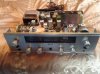
Ok here is a quick at the face, minus the top cover. On this one the top is grey perforated metal, not the optional wood case. The face and chassis are minty, just a little dust.
 

Attachments

  • image.jpg
    image.jpg
    87.3 KB · Views: 42
Chiming in ....

Coupling caps usually keep there leakage once started, but agree on replacing at least the coupling caps.

But what might also have happened was that cathode bias was temporarily lost because of a shorted cathode bypass capacitor for the power stages. Judging from the SX-34 schematic (could also not find an Allied one), they have a common cathode resistor for all 4 power pentodes bypassed by a 50µF 25V electrolytic (C35 in that schematic). Such a cap may have shorted and then 'burnt out', restoring the resistance. I would suggest at least replacing that as well; visual inspection might be revealing. This particularly so if said cap was mounted close to the very hot cathode resistor (electrolytics and heat do not go together very well).

Also guessing (the route I would follow) is suspicion of resistors R51 - R54, again as per the SX-34 schematic. These values are quite high for grid stoppers; might also have failed temporary because of age. But I would first examine the cathode bias stuff - a little suspicious that all four coupling caps would start leaking at the same time, and then again self-heal at the same moment somewhat later ....

(And while busy, you said it was an old set. Tube holders etc, have a habit of becoming oxidised/rusty after time. Some attention thataway may not be in vain.)

But as asked before, kindly do keep us informed! Someone else's experience very informative!

 
The receiver also lost stereo reception during the incident. The stereo light also went out, along with the seperation. Would this indicate anything specifically? Or reinforce the cap meltdown? All the sound quality and functions did return to normal after the incident
 
One more possibility... there are two hum pots connected to the cathode voltage, used to bias these heater windings positive (reduces hum). I've seen these short to ground intermittently, causing red plating.
 
Holy mother of!

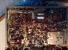
Ok, here is a shot of the belly of the beast! Im guessing the coupling caps are those brown wax cubes??? There is a cluster of them around the power tubes. On a good note, i cannot see any obvious damage such as burnt resistors, bulging or leaking caps. Everything looks as if it were put in there yesterday.
What a twisted nest of components tho...but i WILL get those coupling caps!
Please tell me which they are..
 

Attachments

  • image.jpg
    image.jpg
    127.5 KB · Views: 50
One more possibility... there are two hum pots connected to the cathode voltage, used to bias these heater windings positive (reduces hum). I've seen these short to ground intermittently, causing red plating.

Then I would suggest testing these first. Again, such a fault would let all power tubes red-plate and restore simultaneously.

Problem, if intermittent you will probably find them non-earth-shorting when you measure. Hopefully there is a way of 'unscrewing' them and making sure that there is no possibility of such a short - insulating washers, whetever; I do not know how they are mounted.
 
Last edited:
Then I would suggest testing these first. Again, such a fault would let all power tubes red-plate and restore simultaneously.

Problem, if intermittent you will probably find them non-earth-shorting when you measure. Hopefully there is a way of 'unscrewing' them and making sure that there is no possibility of such a short - insulating washers, whetever; I do not know how they are mounted.

I do believe this was / is the problem. It makes perfect sense...after i fiddled with these and other controls, no more redplating. I still want to restore her tho..beautiful little piece!
 
The brown cubes look like them. If those are ceramic, they are probably electrically OK. Ceramics can fail, but they do so at a much lower rate than say paper capacitors. Plastic body caps may be OK, but it depends what they are. Those don't look like a paper cap to me though.
 
The brown cubes look like them. If those are ceramic, they are probably electrically OK. Ceramics can fail, but they do so at a much lower rate than say paper capacitors. Plastic body caps may be OK, but it depends what they are. Those don't look like a paper cap to me though.

How do i tell if they are ceramic? They are reddish brown rounded cubes. They are covered in a hard waxy coating...not real soft. There are a couple of the paper in oil caps i believe, in the pre section. They are grey Suzuki caps, as somebody mentioned earlier.
 
Ceramic caps are usually obviously a ceramic material. Its typically not glazed, and is usually a red or tan color. Its the same feel as a ceramic plant pot. If they were wax dipped ceramics, its usually a soft wax that you can easily scrape off with your fingernail. Not sure on a hard coating. Its possible that it would be spelled out in the schematic or service manual if you have one. Hopefully someone who has been under the hood of one will know for sure.

If in doubt, you could always test them or just change them. If you don't happen to have a cap tester that can run them up to full voltage to test for leaks, the test results probably won't be all that useful. Personally I do not like how ceramic caps sound, so I wouldn't be opposed to changing them just on principle.
 
Back
Top Bottom