• The move to the new server is done. There are some software and database maintenance updates in process. This has us passing the hat around to help out. We appreciate any donations. Seriously, even a dollar helps. The payment page may be found here - https://www.audiokarma.org/support.html

Teppaz Présence — All voltages too high, EL84 seems to draw insufficient current

PaulOliver

New Member
Hi all,

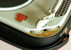
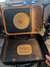
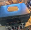
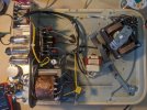
I'm working on a Teppaz Présence portable record player/amplifier and I'm stuck with voltages that are too high everywhere. I've been troubleshooting this on a French forum and I'm hoping fresh eyes might help.

THE CIRCUIT

- EZ80 rectifier → EL84 output stage
- Power transformer secondary: 2 × 350V AC
- Mains input confirmed at 230V, 110/220V selector correctly set (I disconnected the 110/130V leads and wired 0-220V directly to the primary)

MEASURED VS. EXPECTED VOLTAGES

- EZ80 output (1st filter cap): 370V DC (expected ~300V)
- EL84 anode: 360V (expected ~280V)
- EL84 screen grid G2, after 20kΩ: 240V (expected ~220V)
- EL84 cathode: 6.86V (expected ~5.2V)
- EZ80 heater: 7.5V (expected 6.3V)

WHAT I'VE DONE SO FAR

1. Verified mains voltage and 110/220V selector wiring — correct
2. Checked for retrofitted 1N4007 diodes near EZ80 socket — none found
3. Measured cathode resistor (desoldered one leg): 166Ω (spec ~150Ω, only ~4% drift — not the culprit)
4. Replaced the 50µF cathode bypass capacitor with a new 47µF/50V — no change
5. Noticed the main filter cap is 50µF but the schematic calls for 32µF — ordered correct 33µF and 10µF replacements
6. Calculated cathode current: 6.86V / 166Ω ≈ 41 mA — should be closer to 55–56 mA. The EL84 appears to be drawing about 15 mA too little

DIAGNOSIS SO FAR

The EZ80 has relatively high internal resistance. Without sufficient load current, its output voltage rises — which explains why everything reads high. The key question: why isn't the EL84 drawing enough current?

Possible causes discussed:
- Leaky cathode bypass cap weakening the tube (replaced it — no change)
- Oversized filter cap (50µF vs 32µF spec) contributing to higher voltages
- The EL84 itself could be weak/fatigued


Thanks in advance!
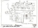
 

Attachments

  • Schema presence.jpg
    Schema presence.jpg
    93.4 KB · Views: 24
Register to hide this ad
I think that high heater voltage is the clue. Do you have a variac? If so, dial it down until you get 6.3 vac across the heater supply and see if the other voltage doesn't fall in line
 
3. Measured cathode resistor (desoldered one leg): 166Ω (spec ~150Ω, only ~4% drift — not the culprit)
4. Replaced the 50µF cathode bypass capacitor with a new 47µF/50V — no change
5. Noticed the main filter cap is 50µF but the schematic calls for 32µF — ordered correct 33µF and 10µF replacements
6. Calculated cathode current: 6.86V / 166Ω ≈ 41 mA — should be closer to 55–56 mA. The EL84 appears to be drawing about 15 mA too little
Could you check #3. I calculate over 11% drift. Also #6. If the expected cathode voltage is 5.2V, why do you say the cathode current should be 55-56 mA? 5.2V/150 ohm => 35 mA

These facts still does nor explain (to me) why you have higher bias and current, yet also higher voltage on the plate. Your wall voltage is 230 Vac and you are connection for 220Vac on the power transformer? That is 4% over voltage and does not explain why your heater voltage is 19% over. Like @gadget73 suggested, double check what you actually have on the power transformer primary. You may need to reduce your input to the transformer, and/or add some resistance in the heater circuit to tame it to 6.3 Vac.

Other suggestions to check,
1. Is the operating point depicted on the schematic correct, i.e. is there another schematic source to compare it to. 5.2 V cathode voltage strikes me as low for a EL84 with 280V on the plate, but I have not checked the load lines since I don’t know the primary characteristics of the output transformer.
2. Check the primary of the output transformer. You are dropping only 10V across the primary in stead of 20V - perhaps there is a short.

Good luck.
 
probably is low, but a lot of things under-biased the tubes for longer life.

The output of the rectifier and heater supply are not quite off by the same level, but its close enough to make me think its realated. 19% over on the heater, 23% at the rectifier. I suspect you'd find the high voltage AC input to the rectifier to be also around 20% high.
 
I think that high heater voltage is the clue. Do you have a variac? If so, dial it down until you get 6.3 vac across the heater supply and see if the other voltage doesn't fall in line
Sadly not, I'm very new to tubes and doesn't have the proper tools for this.
 
I think @gadget73 has it right here- filament and HV both in the +20% ballpark- primary is getting too much voltage. If the EL84 were pulling more current, it would bring down the high voltage, yes, but 20% is excessive, and I really doubt the additional HV loading would bring the filament voltage down 20% as well.

Not sure what country you are in (That info in the "about" of your profile is helpful) but if you don't have lower AC voltage to work with, perhaps you have a 2:1 travel voltage converter transformer? 230 would give you 115V, which you could apply to the 110V tap and be pretty close, or perhaps on the 130V tap to see if the where the voltages land. If you don't have a voltage converter, just as a quick test you could use a higher wattage incandescent light bulb in series with the record player, perhaps a 100W bulb (with a filament, not LED) would provide some useful data. If none of those are handy, there are easy plans around to use a filament transformer to buck the AC voltage down to a more friendly voltage- that would be a good long term solution. Whatever the solution, use the filament voltage as your indication as it would be more independent from the EL84 situation.

I would not worry too much about what bias current the EL84 is pulling- @Selmerdave is correct- this tube is cooking at 14 watts, and probably has been for quite some time- you did not say anything about it's condition, it could be quite worn out and weak. Get the voltages under control, and try a new tube.
 
Could you check #3. I calculate over 11% drift. Also #6. If the expected cathode voltage is 5.2V, why do you say the cathode current should be 55-56 mA? 5.2V/150 ohm => 35 mA

These facts still does nor explain (to me) why you have higher bias and current, yet also higher voltage on the plate. Your wall voltage is 230 Vac and you are connection for 220Vac on the power transformer? That is 4% over voltage and does not explain why your heater voltage is 19% over. Like @gadget73 suggested, double check what you actually have on the power transformer primary. You may need to reduce your input to the transformer, and/or add some resistance in the heater circuit to tame it to 6.3 Vac.

Other suggestions to check,
1. Is the operating point depicted on the schematic correct, i.e. is there another schematic source to compare it to. 5.2 V cathode voltage strikes me as low for a EL84 with 280V on the plate, but I have not checked the load lines since I don’t know the primary characteristics of the output transformer.
2. Check the primary of the output transformer. You are dropping only 10V across the primary in stead of 20V - perhaps there is a short.

Good luck.
166-166*0,1=149, my bad, you're right. 10% drift at least. Thank for correcting me. I heard on some channel that the current on the cathod should be around 55mA, as I'm new in tube I did not twice checked (or maybe misinterpreted) the numbers and you're still right ohm law says 35mA.

On the transformer at primary I'm on 220V yes. I have double check and it is the right connection.

For the schematics I have another link here Électrophone Eco Présence R-Player Teppaz; Lyon, build |Radiomuseum.org wich says 5.2V too.
From the same brand but another similar device they says 8.3V, the cathod resistor and capacitor are by the way not the same value https://radios-tsf.fr/01 schema/Teppaz/sch-Teppaz-Octave.gif

On the primary of the output transformer I have 256 Ohms.

Thank you for your time.
 
I think @gadget73 has it right here- filament and HV both in the +20% ballpark- primary is getting too much voltage. If the EL84 were pulling more current, it would bring down the high voltage, yes, but 20% is excessive, and I really doubt the additional HV loading would bring the filament voltage down 20% as well.

Not sure what country you are in (That info in the "about" of your profile is helpful) but if you don't have lower AC voltage to work with, perhaps you have a 2:1 travel voltage converter transformer? 230 would give you 115V, which you could apply to the 110V tap and be pretty close, or perhaps on the 130V tap to see if the where the voltages land. If you don't have a voltage converter, just as a quick test you could use a higher wattage incandescent light bulb in series with the record player, perhaps a 100W bulb (with a filament, not LED) would provide some useful data. If none of those are handy, there are easy plans around to use a filament transformer to buck the AC voltage down to a more friendly voltage- that would be a good long term solution. Whatever the solution, use the filament voltage as your indication as it would be more independent from the EL84 situation.

I would not worry too much about what bias current the EL84 is pulling- @Selmerdave is correct- this tube is cooking at 14 watts, and probably has been for quite some time- you did not say anything about it's condition, it could be quite worn out and weak. Get the voltages under control, and try a new tube.

Thanks for mentioning about the country and shame on me to not have spoken about it before, I'm in France, usualy here it is 230V, I joined a pic about tension at the wall plug. I have btw updated my profile infos.

1775318629708.png


I have a dim bulb , 60 Watts filament bulb. How it could help in this configuraiton?

I will try to find a new EL84 to replace and see if something change also.
 
If you use the dim bulb tester, the lamp will burn up some of the mains voltage and reduce what the amp gets. Larger bulbs will reduce it by less voltage, not sure what a 60W will do but give it a try and see if the 6.3 vac leads come out close to correct.
 
I have a dim bulb , 60 Watts filament bulb. How it could help in this configuraiton?
Right @gadget73 - My thought was to run the record player off of the dim bulb for a brief period as a test, just to reduce the AC voltage and give you another data point on how the other voltages track. It would just perhaps give you an idea of how much you need to reduce the voltage to achieve an operating point that more closely matches the schematic. Mostly just brain storming. Not a permanent solution- the motor of the record player might not like the lower voltage.
 
For the long term solution, we need to see where all of the voltages settle when you have an EL84 that you trust to be stronger- they may not change much, or they may change "enough".

Your supply voltage of 232V is only about 5-6% higher than the specified 220V, so the very high voltages don't seem to make much sense. Perhaps they will with the stronger EL84. Once we have a better feel for how much we need to reduce the voltage on the primary, the most elegant solution is to add a small filament transformer inside the record player that bucks the AC supply voltage down to the desired value.

Otherwise, corrections would have to be applied to the secondary side, which is more trouble. the filament voltage can be corrected with a very small resistance power resistor in series with the filament- This is a pain in the butt to get right, but it can be done. We can calculate a reasonable value to start with if you decide to do that. Correcting the high voltage is pretty easy- we would add a dropping resistor at the cathode of the rectifier, as shown in the second schematic that you linked to.
 
If you use the dim bulb tester, the lamp will burn up some of the mains voltage and reduce what the amp gets. Larger bulbs will reduce it by less voltage, not sure what a 60W will do but give it a try and see if the 6.3 vac leads come out close to correct.
Thanks for clarification, I ran the measurements again with and without dim bulb, 60W bulb. seems the dim bulb lower a bit too much the cathod DC. the direct current is keeping going lower (1.6V or less, after a couple of minutes).
 

Attachments

  • teppaz presence.png
    teppaz presence.png
    654.3 KB · Views: 5
Hi all,


Some returns to complete this thread.


I have received the parts plus an another device for spare parts.

After changing all capacitors the problem was still here (high voltages). But I started to check the resistors and it was really a mess, some had twice the value, I later searched the net to find some informations and these kind of resistors called carbon resistor doesn't age well.

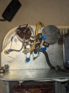
I had to add a small transformer on input to lower voltage from 230V to 220V which helped a lot.

Finally after replacing all capacitors and all resistors voltages started to match the schematic. Except for the 280V on EL84 which is around 310V, I changed the output transformer and it falled down to 300V, the old transformer was 200 Ohms on primary versus 400Ohms on "new" one (from an another old Teppaz). I suspect the EL84 which should be around 50 years old, I don't have spare part for this one now.

I have 220V on the 8uF (10uF now with new cap) which indiquate me the EZ80 is not faulty.

So now everything is working fine except I got a humming in the speaker, I double checked ground and everything seems ok, It is also humming when the device is plug, and it changes nothing when I turn it on and change the volume which is maybe the input transformer or the fact that the plug is not grounded, if someone have ideas?

Thanks anyway for suggestions and help.
I'm happy with it.


1776492015511.jpeg1776492040627.jpeg
 
I was going to mention that I thought the new transformer was too close to the output transformer, but it was pretty late here- Great find there! Now you understand why the placed the output transformer and the power transformer on opposite sides.

Now that you have the voltages under control (Excellent work by the way) replacing the EL84 is an important next step- (presuming this one is weak), the new tube may pull more current and cause the voltage at the plate to be more inline with what you are expecting.

Replacing the output transformer was likely not necessary- The transformer windings don't drift in resistance, and with the voltages being more correct given your new transformer the original output transformer would probably be just fine. With the EL84 pulling more current the plate voltage will be lower.
 
It is possible to have an internal turn to turn short in an output transformer which changes DC resistance but that has a huge effect on the AC signal. If it played, fair bet it wasn't shorted. A turn to turn short will basically kill the audio output

400 ohms seems like an awful lot of DC resistance in an output transformer
 
Back
Top Bottom