• The move to the new server is done. There are some software and database maintenance updates in process. This has us passing the hat around to help out. We appreciate any donations. Seriously, even a dollar helps. The payment page may be found here - https://www.audiokarma.org/support.html

Testing as preamp from Integrated amp?

ReisDaddy

Active Member
Hello, i want to try my integrated amplifier Marantz PM-750 DC as a preamp. I want to play around with older Marantz and Sansui that has "Main IN" RCA to plug.

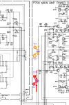
I did research in AK, i found abit information that we can do it , and we must know where the audio line before to main amp. I want to make sure is this the correct position?
Orange is Left channel line.
Red is right channel line.
Blue where i cut/separate

And do i need to put Capacitor BP like maybe 10uF 25v, its what i see in schematic of Marantz 1180 DC right after MAIN IN pin in series?

Schematic_zoom.png

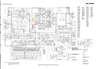
Full schematic

Schematic.png

Thank you very much.
 
Register to hide this ad
And do i need to put Capacitor BP like maybe 10uF 25v, its what i see in schematic of Marantz 1180 DC right after MAIN IN pin in series?

To me that would appear unnecessary, as the outputs of both opamp stages (one for enabled, one for defeated eq) would arready appear to have coupling caps anyway - and the same would appear to go for the inputs of the power-amp section. However, I have some doubts, whether the PM750DC would be a really ideal candidate for such a modification, as the output impedance of the pre-amp section would appear quite high. So personally I'd rather tend to leave it as is.

Greetings from Munich!

Manfred / lini
 
I agree. It can be done with some integrated amps, but I wouldn't attempt it with this one. I had a Marantz model 1030 that had pre-out and main-in jacks in the earlier version. Mine was a later version where they omitted them. So it was easy for me to add a set of jacks to it since other than omitting the jacks in the later version they were both the same.
 
Hello, i want to try my integrated amplifier Marantz PM-750 DC as a preamp. I want to play around with older Marantz and Sansui that has "Main IN" RCA to plug.

I did research in AK, i found abit information that we can do it , and we must know where the audio line before to main amp. I want to make sure is this the correct position?
Orange is Left channel line.
Red is right channel line.
Blue where i cut/separate

And do i need to put Capacitor BP like maybe 10uF 25v, its what i see in schematic of Marantz 1180 DC right after MAIN IN pin in series?

View attachment 3268856

Full schematic

View attachment 3268855

Thank you very much.
That's where I'd put it. Make sure a cap, DC blocking, precedes pre out, if not insert cap there. Pre out in any configuration should not have DC on it, signal only.
 
Thank you guys for all your input.

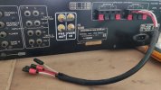
I did manage to make it as pre amp. Luckily, there is a jumper right before the power amp area.

Successfully with the help at other forum. I dont know its ethic or not here to name other forum?

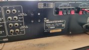
IMG_20240812_131757.jpg

Make holes, using stepped drill bit.


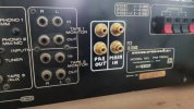
IMG_20240812_160219.jpg

And get jumper idea from Marantz 22xx

IMG_20240812_162603.jpg

Yay... PM-750 DC SE
SE = Special Edition :D

@lini is there a way to measure the output impedance? I dont have oscilloscope. Only DMM.

I did test the pre amp with Sansui AU 517 as power amp. It is better now, i can listening to them longer than before.
I dont know why the Sansui 517 make me fatigue, very tired. The first time in my life i know fatigue. I thought its just an overreacted people commenting about speaker or reviewer.

Then unlucky, my Sansui 517 left channel start making trouble. i did not check them yet. I'll make a separate thread about that later.
 
Successfully with the help at other forum. I dont know its ethic or not here to name other forum?

No worries, that shouldn't be a problem.

@lini is there a way to measure the output impedance? I dont have oscilloscope. Only DMM.

There is, but you'll need more than just the DMM for the purpose.

I'd first suggest to have a look, which frequency range your DMM would support for AC voltage measurements (that should be mentioned in its manual) - so you know what test frequency to choose for a reliable measurement. And as test signal generator you could for example simply use some sort of computer (PC, notebook, tablet, smartphone...) with a suitable software (like for example the frequency generator in Audacity or the web browser in combination with one of the frequency generators available on the web or whatever - doesn't really matter, as it just needs to be able to provide a sine wave output signal to feed one of the line-level inputs of the Marantz with). And of course you'd set the volume on both the generating device and the Marantz low enough, so that the output signal won't be clipped.

Well, and then you'll need some suitable load resistance, be that a fixed resistor or a pot, to hook between signal and signal ground of the pre-amp output. In case of a pot, the contacts to use would be one of the ends and the wiper contact- and in case of a fixed resistor, its value shouldn't be all too large compared to the expected output impedance (in your case I'd probably first try with an 1 kOhm resistor).

And then you simply make use of the laws of voltage division, namely the equation: load resistance / (load resistance + output impedance) = voltage over load resistance / total voltage (with the total voltage being the voltage, that you measure without the load resistance hooked to the pre-amp output - i.e. the unloaded or respectively idle output voltage). That equation can be transformed into: output impedance = ((total voltage / voltage over load resistance) - 1) * load resistance.

And if one is using a pot, one can of course also adjust the pot, until the voltage drop at the pot is exactly half the value of the idle/unloaded voltage, that one has measured before - because then the term in brackets boils down to ((2 / 1) -1) = 1, so that the output impedance is equal to the adjusted load resistance. And hence one wouldn't even need to calculate, but could simply measure the adjusted resistance of the pot (after removing it from the pre-amp out again, of course), as it would then be just the same as the output impedance.

Greetings from Munich!

Manfred / lini

 
@lini I did ask ChatGPT, their answer is like this:

chatgpt-calculate-impedance.jpg

I just plan to ask you before you answer the way to calculate, to make sure, because as the chatgpt always tell us do not rely 100% to the result.

Is that what you mean? ChatGPT said 10K instead of 1K?

i did have apps from android frequency generator. I will try that.

And how we know the result is too high or not?

Thank you so much
 
Well, that's basically the same approach and the same formula.

And the reason, why I've suggested a lower load resistance is accuracy, as a pre-amp might as well happen to have a pretty juicy output with pretty low output impedance, like for example just 50 Ohm. Now let's assume the generator output level and pre-amp volume control being adjusted for 1 V at the pre-amp output without load. Then the expected voltage drop at a load resistor with exactly 10 kOhm would be 1 V * (10000 Ohm / 10050 Ohm) = an all so tiny tad over 0,995 V. Now let's assume we'd use a 2000 count DMM with an accuracy of for example +/- 0.8 % of the reading plus 5 digits in the 2 V AC range. Then the error could be up to +/- 0.013 V. That's more than the expected difference between the unloaded and the loaded output voltage - and while we could hope for the DMM to err the same way in case of both measurements, so that the result of the calculation wouldn't be skewed quite as badly, that's not guaranteed. Whereas in case of a 1kOhm resistor we'd expect a bit over 0.952 V instead - so that the difference would at least not be within the measuement error range anymore.

Greetings from Munich!

Manfred / lini
 
Back
Top Bottom