• The move to the new server is done. There are some software and database maintenance updates in process. This has us passing the hat around to help out. We appreciate any donations. Seriously, even a dollar helps. The payment page may be found here - https://www.audiokarma.org/support.html

Testing Marantz output transistors ?

CavScout

Super Member
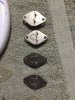
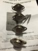
I have never tested out put transistors before but I would like to do so as I am replacing the amp board in my 2238 .
(Yes I did take a photo of their position for reinstall)

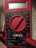
I am hoping that someone can help guide me through the procedure for using my voltmeter as shown in the photo.
I did find some YouTube videos but they talk a bit over my head and they are using a different voltmeter that I am so I am confused by it.
Any help would be greatly appreciated
 

Attachments

  • image.jpeg
    image.jpeg
    68.2 KB · Views: 103
  • image.jpeg
    image.jpeg
    86 KB · Views: 115
  • image.jpeg
    image.jpeg
    45.6 KB · Views: 107
Register to hide this ad
If you really want specific information about your transistors and match the new replacements, buy a Peak Atlas DCA55.

It is worlds ahead of the simple diode test feature of a multi-meter, it will be the best money your spend for transistor testing - Chris
 
Learn how to do it on a multimeter with the diode test first (I've had a rare transistor or two pass a test with the DCA55 yet fail the DMM diode test).
 
Thank you for sending that link but the very first paragraph says not to use the multimeter that I am using because it is a piece of crap.
I won't be able to buy another multi metre for a couple of days so I was hoping to get this work done this weekend.
Does anyone out there know how to test with the multi metre that I have?
 
Lost :-(
The link also says to find out the emitter and collector by looking up the part # or the schematic ( or figure it out on your own)
 
Set your meter to the diode position down at about 5:30. When you short the leads together it should beep or at least read 0.00 on the display. Across a junction it should read something between 0.45 and 0.7 Measure an ordinary diode first, both ways. Those are the two readings you should see when measuring a transistor. Try following the instructions in the link and see what you get.

I haven't read the link in a while, but it's a bit of trial and error. For metal TO-3 transistors you know the case is always the collector. It's a matter of trying combinations to decide if it's an NPN or PNP and what the other two leads are. Hint- you can always look it up first, then it's just a matter of deciding it's good or bad!
 
The forward direction should be the lower reading. Reverse direction should be high. Anything completely shorted is a bad device. Think of the transistor as two diodes. For an NPN, they join at the base and point away. For a PNP they join at the base and point towards.
 
Ok , I have it figured out now .

These are the values that I have determined and now I am wondering if they are good or of concern

1)
collector .554
emitter .561

2)
collector .546
emitter .551

3)
collector .499
emitter .509

4)
collector .509
emitter .525
 
If you have the postive lead on the base, those would be good numbers for four NPN devices. If you have the negative lead on the base, those would be good numbers for four PNP devices! You should also measure from collector to emitter in both directions, expecting a high reading. Every now and then you find a bad device that measures good except for that. It's very rare, but I've had it happen.
 
Back
Top Bottom