

You are using an out of date browser. It may not display this or other websites correctly.
You should upgrade or use an alternative browser.
You should upgrade or use an alternative browser.
Testing STK Modules?
- Thread starter Brivan
- Start date
Register to hide this ad

whoaru99
Epic Member
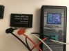
I recently stumbled upon an Ebay listing for an STK-0080 Darlington power pack. The seller provided this image to prove the module as being good. I had no idea these could be tested with a transistor/semiconductor checker. Is this a valid testing method for STK modules?
View attachment 1739742
I don't know the specifics of the test method but, regardless, if it is the module itself you are interested in the odds are high (some may opine nearly certain) it is fake/counterfeit; regardless that a test may show functionality.
The fakes may "work"...for a while, but are not nearly as durable or reliable as the originals.

Brivan
Well-Known Member
Given the rarity and uncertainty of finding an OEM STK module, I've resigned myself to the fact that the replacements I purchase are likely going to be non-OEM, which I'm fine with. I have a few receivers with replaced STK modules and they've all worked just fine. For my own listening purposes, I don't turn the volume up on any of my receivers past the 10 o'clock position and I think under-driving them is beneficial to their lifespan.I don't know the specifics of the test method but, regardless, if it is the module itself you are interested in the odds are high (some may opine nearly certain) it is fake/counterfeit; regardless that a test may show functionality.
The fakes may "work"...for a while, but are not nearly as durable or reliable as the originals.
I've pulled a few STK modules, thinking they were bad, only to find out (after replacing several other amp board components) they were actually okay. With that, I was interested in a reliable method to test them - as shown in the photo of the previous message. But I don't know if the testing method in that photo is actually valid.

That test being done in the picture seems strange. I don't see how pin 2 to pin 8 and pin 9 will show up as a transistor junction as shown.
The only test I do on chips like that is a quick ohm check between pin 2 and 3, as well pins 8 to 9. Usually those pin pairs show a short in a failed STK. In fact those 2 sets of pins are good checks on most single channel STK hybrids as they are checking the E to C junction for the NPN side output as well as the PNP side output of those chips, whick is where 1 usually shorts in a failed STK.
See attached sheet that shows pin outs on many STK's
The only test I do on chips like that is a quick ohm check between pin 2 and 3, as well pins 8 to 9. Usually those pin pairs show a short in a failed STK. In fact those 2 sets of pins are good checks on most single channel STK hybrids as they are checking the E to C junction for the NPN side output as well as the PNP side output of those chips, whick is where 1 usually shorts in a failed STK.
See attached sheet that shows pin outs on many STK's
Attachments
Brivan
Well-Known Member
Thanks for the info! I know I've discovered at least one bad STK that had pins 2 & 3 shorted together. Oddly-enough, some of the resistance measurements I had taken between various pins of known good STKs wouldn't compare exactly with the same resistance check done on other known good STKs of the same type. There weren't in huge differences in resistance measurements between one STK and another, but it was enough to make me wonder why there was a variance between them.That test being done in the picture seems strange. I don't see how pin 2 to pin 8 and pin 9 will show up as a transistor junction as shown.
The only test I do on chips like that is a quick ohm check between pin 2 and 3, as well pins 8 to 9. Usually those pin pairs show a short in a failed STK. In fact those 2 sets of pins are good checks on most single channel STK hybrids as they are checking the E to C junction for the NPN side output as well as the PNP side output of those chips, whick is where 1 usually shorts in a failed STK.
See attached sheet that shows pin outs on many STK's
Most of my STK module work has been done on Fisher RS-2010 receivers. They seem to have frequent issues with blown STK modules - mostly from uneven contact with the heat sinks, it appears.

Super Noob
Super Member
That is my pack... it works.
100% original
https://audiokarma.org/forums/index.php?threads/project-fisher-rs-2010.855391/
Do yourself a favor and build the modules... the bones of the RS-2010 deserves it.
100% original
https://audiokarma.org/forums/index.php?threads/project-fisher-rs-2010.855391/
Do yourself a favor and build the modules... the bones of the RS-2010 deserves it.
Last edited:
Brivan
Well-Known Member
Glad to hear from you! I was kinda hoping the seller of that STK module would also be here on AK. I did some poking around here, but didn't find anything about using a transistor checker on an STK module, so I was wondering if it was a valid test. I had a look at your RS-2010 rebuild thread - nice job. The RS-2010s are great-looking receivers and I would like to try replacing the STK modules with the discrete component kit some time. I've gone so far as to re-mill the surfaces of the heat sinks for better contact between them and the STKs since the heat sinks seem to warp over time.That is my pack... it works.
100% original
https://audiokarma.org/forums/index.php?threads/project-fisher-rs-2010.855391/
Do yourself a favor and build the modules... the bones of the RS-2010 deserves it.
Brivan
Well-Known Member
A note of interest: I recently acquired an SX-780 that was in protection mode. I checked the output modules and found the right-hand module to have excessive voltage readings on pins 1, 3, 8 & 0. I pulled the module and found it failed one of the resistance checks (between pins 1 & 3, which is normally around 3.3K or so). The receiver came out of protection with the bad module removed. I connected up my semiconductor analyzer to pins 2, 8 & 9 of the bad module and it tested good. I did the same check on two other known good modules and they tested good, as well. I checked a few other voltages on the main board, then replaced the module with one of the good spares. The receiver works fine, now. Considering where I found the "open" on the bad STK module, it makes sense that my analyzer didn't detect anything wrong.


the checkout of pin 2 and 3, as well as 8 and 9 refers to STK0050 type STKs. Your STK078 are different.
Fot the STK078
Power off and unplug the receiver
To check for a short measure between pin 7 and 8, then check pin 7 to pin 9, usimg an ohm meter. If either of these checks show low resistance, the hybrid IC is bad. Of course checking for shorts using an ohm meter requires the unit to be off and unplugged.
If those ohm readings are OK (should be very high if not open/overload), then you could have another problem.
Power on the unit and Check for +24v on pin 8, and -24vdc at pin 6. If either is missing, you may have a power supply problem like bad diodes.
If OK then unplug the unit and check These 4 resistors near those 2 hybrids. R753, R752, R853, R852. use an ohm meter and verify that each measures 100 ohms. They are usually fusable types that can open.
Good luck
Fot the STK078
Power off and unplug the receiver
To check for a short measure between pin 7 and 8, then check pin 7 to pin 9, usimg an ohm meter. If either of these checks show low resistance, the hybrid IC is bad. Of course checking for shorts using an ohm meter requires the unit to be off and unplugged.
If those ohm readings are OK (should be very high if not open/overload), then you could have another problem.
Power on the unit and Check for +24v on pin 8, and -24vdc at pin 6. If either is missing, you may have a power supply problem like bad diodes.
If OK then unplug the unit and check These 4 resistors near those 2 hybrids. R753, R752, R853, R852. use an ohm meter and verify that each measures 100 ohms. They are usually fusable types that can open.
Good luck
While it could happen, I doubt that Both IC's have failed the same way. Feel free to send me a PM if you need more help. I wouldnt just swap out thos 2 STK's. You need to test to see if they are indeed bad.the checkout of pin 2 and 3, as well as 8 and 9 refers to STK0050 type STKs. Your STK078 are different.
Fot the STK078
Power off and unplug the receiver
To check for a short measure between pin 7 and 8, then check pin 7 to pin 9, usimg an ohm meter. If either of these checks show low resistance, the hybrid IC is bad. Of course checking for shorts using an ohm meter requires the unit to be off and unplugged.
If those ohm readings are OK (should be very high if not open/overload), then you could have another problem.
Power on the unit and Check for +24v on pin 8, and -24vdc at pin 6. If either is missing, you may have a power supply problem like bad diodes.
If OK then unplug the unit and check These 4 resistors near those 2 hybrids. R753, R752, R853, R852. use an ohm meter and verify that each measures 100 ohms. They are usually fusable types that can open.
Good luck
Doesn't appear to be the STKs. the pin 7 to 8/7 to 9 all tested in mega ohms, the four resistors measure 100 ohms. The only measurement that was off was the voltage at pins 6 & 8 which were all around +/-31.3 or 31.4.
Also found this when I took the bottom cover off. Something leaked, maybe a filter cap? I'll look at the exploded view to figure out how to check the bottom of the filter caps, which are hidden.

Also found this when I took the bottom cover off. Something leaked, maybe a filter cap? I'll look at the exploded view to figure out how to check the bottom of the filter caps, which are hidden.

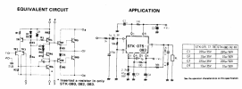
Testing pins 7/8 and 7/9 tests TR12 and TR10 (see equivalent circuit in datasheet)
Some additional tests you can run are,
Pin 9(red) Pin 7(blk) tests TR10be expect xxxohms
Pin 9(blk) Pin 7(red) tests TR10be expect OL
Pin 6(red) Pin 7(blk) tests TR13ce expect OL
Pin 6(blk) Pin 7(red) tests TR11ce, TR13ce expect OL
Pin 5(blk) Pin 7(red) tests D5, TR11be expect xxxxohms
Pin 0(red) Pin 9(blk) tests TR6ce expect OL
Some additional tests you can run are,
Pin 9(red) Pin 7(blk) tests TR10be expect xxxohms
Pin 9(blk) Pin 7(red) tests TR10be expect OL
Pin 6(red) Pin 7(blk) tests TR13ce expect OL
Pin 6(blk) Pin 7(red) tests TR11ce, TR13ce expect OL
Pin 5(blk) Pin 7(red) tests D5, TR11be expect xxxxohms
Pin 0(red) Pin 9(blk) tests TR6ce expect OL
That's the plan, have to do more disassembly to get a view.Something may have been spilled into/on the unit in question. Look for residue on circuit boards & such inside.
So the high ohms is telling me those transistors aren't open?Testing pins 7/8 and 7/9 tests TR12 and TR10 (see equivalent circuit in datasheet)
Some additional tests you can run are,
Pin 9(red) Pin 7(blk) tests TR10be expect xxxohms
Pin 9(blk) Pin 7(red) tests TR10be expect OL
Pin 6(red) Pin 7(blk) tests TR13ce expect OL
Pin 6(blk) Pin 7(red) tests TR11ce, TR13ce expect OL
Pin 5(blk) Pin 7(red) tests D5, TR11be expect xxxxohms
Pin 0(red) Pin 9(blk) tests TR6ce expect OL
What does the 7 extra volts at pin 6 & 8 tell? me
Yeah and also not short.So the high ohms is telling me those transistors aren't open?
Components can fail short or open. Above tests are trying to verify b-e and c-e junctions.
Expect b-e to test like a diode ie, 0.6V or OL depending on probe orientation.
c-e junction should not be short.
If you look at the equivalent circuit and each pin in turn you can try and work out if a meaningful test can be performed between which pins.
I wouldn't worry about the 7 extra volts on 6 and 8. But I am concerned about what may have leaked. (possibly bad primary filter cap). This can easily cause a hum, but not sure if it will produce -28v at the output. As another check set your voltmeter for AC and check pins 6 and 8. See if you have sizable AC on either pin. If you do, one of your primary Filter caps is open.So the high ohms is telling me those transistors aren't open?
What does the 7 extra volts at pin 6 & 8 tell? me