primosounds
Powered with pure tube sounds.
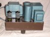
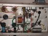
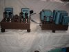
For all you tube amp fans, here is my latest amp. I call this an RH87 after the "RH amps" designed by Alek Kitic. Many thanks to Mr. Kitic and Kward who were instrumental in helping to get this amp finished.
A little background for those unfamiliar with Aleksandar Kitic, his design of the famous, or infamous, depending on your point of view, "rh84" single ended amp based on what was once the lowly and ignored single ended amp from a console stereos which were the staple audio entertainment of suburbia in the 60s and 70s. His popular RH84 single ended amp design uses plate to plate feedback instead of "global negative fb" like used in the EICO AF4 integrated amp or the Magnavox se EL84 amp. This type of fb goes from the plate of the output tube to the plate of the driver tube.
The "87" part of the amp relates to the EICO HF87 output transformers that i used in the amp. The RH circuit i followed belongs mostly to the "RH Universal" EL34/6550 single ended amp which i adapted to a Push pull output stage. This is accomplished with the use of the Lundahl LL1544A input/splitter transformers. These transformers splits the input signal into 2 mirror imaged signals instead of using a tube for phase splitting. The EICO HF87 uses a long tailed pair phase inverter, which consists of a 12ax7 to 6sn7 which splits the signal to the pair of EL34 output tubes.
Why use an IT, input transformer? Well, with a modern IT, phase splitting is almost perfect! ITs have been around a long time and are a staple of the broadcast and recording industries. A tubed based phase splitter is imperfect and all you need to do is search the subject and you will find out why. For me, the audio artifacts that are present in a tube phase splitter was not enough to out weigh the increased power. In other words, quality vs. quantity.
The RH87 uses the IT to split the signal into phase and antiphase signals. Each type of signal is fed to one section of the 6SL7 driver tube and then to the pair of EL34. Since the HF87 OPTs are UL, ultra linear, i also used that feature to simplify the design. Essentially the amp is 4 single ended EL34 amps that are driven by the 2 6SL7 driver tubes. An unusual feature for the RH type amps that use cathode bias, is the use of fixed bias. I employed this as a means to a few more watts of power and to allow precise adjustment of the operating current of the output tubes, be it EL34, 6550, KT88, KT90, or 6L6.
Critical to any amplifier design is the power supply. I like to use tube rectifiers since they allow more flexibility in voltages by switching to different types of rectifiers. And more importantly they allow a slow voltage ramp up when using indirectly heated rectifiers like the 5ar4 vs the directly heated rectifiers like 5u4.
The power supply consists of a 500-0-500 @ 400ma x 6.3v x 5.0 @ 6A power trans. The high voltage is fed to a cLCLC filter consisting of 2.0uf x 630 pio to 5H @ 500ma choke to100 uf ASC oil cap to 8H @ 200ma choke to 150uf ASC motor run oil cap. Bias voltage is achieved by reverse installing a 12.6v filament trans into CLCRCRC filter. The caps in the bias supply are also film caps, so, there is not a single electrolytic capacitor in the amp. All of this heavy metal required a 2 chassis amplifier.
Operating conditions for EL34 tubes are 350v B+ for a 340Av operated at 70ma cathode current. I estimate power output of about 22 watts of class A quality. The amp is dead quiet and it sounds like a very clean single ended amp with lots of power.
One of the goals of my build was exploring the results of using a SE amp design in a PP output stage to achieve a better sound quality. I love the SE sound, which to me is more natural, emotionally involving and less fatiguing. Much of that quality is the result of the 2nd harmonics present in the output of a SE amp. PP amps by their design can achieve more power by operating in class AB and sound cleaner by the 2nd harmonic cancellation which is achieved when the phase and antiphase signals are recombined in the output transformer. The drawback is the artifacts from the phase splitter and crossover distortion in the output transformer, the uncancelled third harmonics and the effect of global negative feedback. All of these factors leave a sonic fingerprint and can dominate the audio spectrum. To my ears, the RH87 has none of these drawbacks. It sounds like a SE EL34 or 6550 amp with twice the power. A


 ll in all i am more than pleased with the results. cheers, Dak
A little background for those unfamiliar with Aleksandar Kitic, his design of the famous, or infamous, depending on your point of view, "rh84" single ended amp based on what was once the lowly and ignored single ended amp from a console stereos which were the staple audio entertainment of suburbia in the 60s and 70s. His popular RH84 single ended amp design uses plate to plate feedback instead of "global negative fb" like used in the EICO AF4 integrated amp or the Magnavox se EL84 amp. This type of fb goes from the plate of the output tube to the plate of the driver tube.
The "87" part of the amp relates to the EICO HF87 output transformers that i used in the amp. The RH circuit i followed belongs mostly to the "RH Universal" EL34/6550 single ended amp which i adapted to a Push pull output stage. This is accomplished with the use of the Lundahl LL1544A input/splitter transformers. These transformers splits the input signal into 2 mirror imaged signals instead of using a tube for phase splitting. The EICO HF87 uses a long tailed pair phase inverter, which consists of a 12ax7 to 6sn7 which splits the signal to the pair of EL34 output tubes.
Why use an IT, input transformer? Well, with a modern IT, phase splitting is almost perfect! ITs have been around a long time and are a staple of the broadcast and recording industries. A tubed based phase splitter is imperfect and all you need to do is search the subject and you will find out why. For me, the audio artifacts that are present in a tube phase splitter was not enough to out weigh the increased power. In other words, quality vs. quantity.
The RH87 uses the IT to split the signal into phase and antiphase signals. Each type of signal is fed to one section of the 6SL7 driver tube and then to the pair of EL34. Since the HF87 OPTs are UL, ultra linear, i also used that feature to simplify the design. Essentially the amp is 4 single ended EL34 amps that are driven by the 2 6SL7 driver tubes. An unusual feature for the RH type amps that use cathode bias, is the use of fixed bias. I employed this as a means to a few more watts of power and to allow precise adjustment of the operating current of the output tubes, be it EL34, 6550, KT88, KT90, or 6L6.
Critical to any amplifier design is the power supply. I like to use tube rectifiers since they allow more flexibility in voltages by switching to different types of rectifiers. And more importantly they allow a slow voltage ramp up when using indirectly heated rectifiers like the 5ar4 vs the directly heated rectifiers like 5u4.
The power supply consists of a 500-0-500 @ 400ma x 6.3v x 5.0 @ 6A power trans. The high voltage is fed to a cLCLC filter consisting of 2.0uf x 630 pio to 5H @ 500ma choke to100 uf ASC oil cap to 8H @ 200ma choke to 150uf ASC motor run oil cap. Bias voltage is achieved by reverse installing a 12.6v filament trans into CLCRCRC filter. The caps in the bias supply are also film caps, so, there is not a single electrolytic capacitor in the amp. All of this heavy metal required a 2 chassis amplifier.
Operating conditions for EL34 tubes are 350v B+ for a 340Av operated at 70ma cathode current. I estimate power output of about 22 watts of class A quality. The amp is dead quiet and it sounds like a very clean single ended amp with lots of power.
One of the goals of my build was exploring the results of using a SE amp design in a PP output stage to achieve a better sound quality. I love the SE sound, which to me is more natural, emotionally involving and less fatiguing. Much of that quality is the result of the 2nd harmonics present in the output of a SE amp. PP amps by their design can achieve more power by operating in class AB and sound cleaner by the 2nd harmonic cancellation which is achieved when the phase and antiphase signals are recombined in the output transformer. The drawback is the artifacts from the phase splitter and crossover distortion in the output transformer, the uncancelled third harmonics and the effect of global negative feedback. All of these factors leave a sonic fingerprint and can dominate the audio spectrum. To my ears, the RH87 has none of these drawbacks. It sounds like a SE EL34 or 6550 amp with twice the power. A
ll in all i am more than pleased with the results. cheers, Dak