• The move to the new server is done. There are some software and database maintenance updates in process. This has us passing the hat around to help out. We appreciate any donations. Seriously, even a dollar helps. The payment page may be found here - https://www.audiokarma.org/support.html

The Fisher 70-RT Repair

Is it dangerous to hollow out the can and put the 2 caps inside of it?

And why didn't anyone laugh at my #14 post except Boochie?
I wouldn't restuff the can if a new one is available.

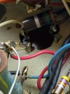
I hope you have a photo of the wiring before you remove the can. It'll make refitting the new one much easier.

:thumbsup:
 
If you’re only concerned with lighting up the eye tube, then why bother restuffing? That’s just more work. And I’m an avid restuffer! For aesthetics, you can remount the original can without making the connections.
 
I hope you have a photo of the wiring before you remove the can. It'll make refitting the new one much easier.
Yes I took photos and not only that, I made a detailed diagram.

Now before I order the C69 Capacitor are you guys sure it is necessary with the values my cans are showing. Please look at my second diagram.

I've included pics of the tops of the cans if that helps determine how old they are?
 

Attachments

  • 17cdc11a-b5ae-4c21-8c46-75455c6cdfd6.jpg
    17cdc11a-b5ae-4c21-8c46-75455c6cdfd6.jpg
    97.8 KB · Views: 15
  • 59dfae76-bb12-42e9-914f-6e72e93b03af.jpg
    59dfae76-bb12-42e9-914f-6e72e93b03af.jpg
    75.2 KB · Views: 16
  • 946847c3-9129-482f-958e-8272b886c01e.jpg
    946847c3-9129-482f-958e-8272b886c01e.jpg
    70.3 KB · Views: 13
  • 6e76d15a-a9bd-4491-b3c5-3f266f173e35.jpg
    6e76d15a-a9bd-4491-b3c5-3f266f173e35.jpg
    77.6 KB · Views: 12
Yes I took photos and not only that, I made a detailed diagram.

Now before I order the C69 Capacitor are you guys sure it is necessary with the values my cans are showing. Please look at my second diagram.

I've included pics of the tops of the cans if that helps determine how old they are?
That's up to you. But I thought the Magic Eye wasn't working. Weren't the cap cans implicated in the problem?

You can put them back in and see if you can get the Eye to work.
 
Last edited:
You can put them back in and see if you can get the Eye to work.
No the cans were not 100% implicated it's just that they are connected to the main tube and removing the main tube made the DBT go dim.

My questions is what do you think of those numbers?

I do not know the tolerances for Tube Stereo Can Caps? is it 5% or 20% ???
 
No the cans were not 100% implicated it's just that they are connected to the main tube and removing the main tube made the DBT go dim.

My questions is what do you think of those numbers?

I do not know the tolerances for Tube Stereo Can Caps? is it 5% or 20% ???
The numbers may not mean much, since the cans aren't being tested in a powered-up circuit.

Put the cans back in and see if you can fix the Magic Eye. That is the only way you'll know for sure.
 
if you want to confirm they are bad, do what I said in post 9, or find someone who has a cap tester that can run at full rated voltage. Short of that, the only other thing to do is throw a set in there and hope for the best.
 
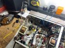
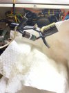
Here it is all cleaned up and ready to reassemble.

Since the C70 Capacitor will be two separate Capacitors upon reassembly does the (Brown Green Black Silver) resistor that goes between the two leads on the C70 cap need to go back in or can it just be omitted?
 

Attachments

  • d8a44299-f221-4adb-a652-a8b3be6715b5.png
    d8a44299-f221-4adb-a652-a8b3be6715b5.png
    560.3 KB · Views: 6
  • 07fc9295-77cb-4cf2-a30d-83b5731064a4.jpg
    07fc9295-77cb-4cf2-a30d-83b5731064a4.jpg
    89.4 KB · Views: 6
  • f3294d35-20d8-418b-9188-a77a30541846.jpg
    f3294d35-20d8-418b-9188-a77a30541846.jpg
    152.4 KB · Views: 5
Last edited:
It has to go back!

If you look at the schematic Gadget posted in #15, you can see it is placed between the positive terminals of the 2 caps of C-70. Since the can itself was grounded to the chassis, you must do the same with the negative terminals of the replacement caps. Just tie them together and solder to the lug of the now "dummy" can that you'll re-install. Make sure it is well grounded.

Before you solder anything, situate all the components and check in just to make sure.
 
Does this look right. The top is what it use to look like and the bottom is what it is now with the two separate capacitors.

The bottom left corner of the old Can Cap measured 634 uf so I assume it is the 500 uf end. The upper right corner of the old Can Cap measured 1201 uf so I assume it was the 1000 uf end.
 

Attachments

  • 1f7477b4-379b-4df2-8ff5-115d563759dc.jpg
    1f7477b4-379b-4df2-8ff5-115d563759dc.jpg
    72.2 KB · Views: 16
  • e821e75a-1da1-4caa-befe-e5f1f3cd0b6f.jpg
    e821e75a-1da1-4caa-befe-e5f1f3cd0b6f.jpg
    126.1 KB · Views: 18
Last edited:
Kinda hard to make out all the connections but it looks good. One comment: best practice is to not have floating connections. The positive terminal of the black cap connected to the 15ohm resistor, connected to the white wire seems to be just that. If you could extend that close terminal strip to serve as a solid tie point, the danger of inadvertently shorting the whole thing out would be greatly reduced.
 
Kinda hard to make out all the connections but it looks good. One comment: best practice is to not have floating connections. The positive terminal of the black cap connected to the 15ohm resistor, connected to the white wire seems to be just that. If you could extend that close terminal strip to serve as a solid tie point, the danger of inadvertently shorting the whole thing out would be greatly reduced.
Not sure what you are saying here? I will be putting heatshrink on all the exposed Positive ends. As long is the wiring is correct in the diagram I made is good, is what I care about right now. I will finish the work after the new C69 Can Cap gets here.
 

Attachments

  • a987248c-c8a9-4811-b417-904cce1acb98.jpg
    a987248c-c8a9-4811-b417-904cce1acb98.jpg
    88.9 KB · Views: 2
  • 7ec28598-7b7a-494f-806d-855debc070f1.jpg
    7ec28598-7b7a-494f-806d-855debc070f1.jpg
    84.5 KB · Views: 2
Back
Top Bottom