• The move to the new server is done. There are some software and database maintenance updates in process. This has us passing the hat around to help out. We appreciate any donations. Seriously, even a dollar helps. The payment page may be found here - https://www.audiokarma.org/support.html

The Fisher 70-RT Repair

Gentlemen
I’ve followed this saga even after bowing out at post #17.
Time to chime back in. The switch is a two pole single throw switch. Fisher used this set up in many units.
One side of the line cord feeds both poles(the jumped pair). The other side of the switch feeds one side of both of the non-polarized outlets and the fuse.
The other wire from the line cord connects to the other side of the non-polarized outlets and one side of the power transformer.
Locate the two black wires from the transformer.
Have your volt meter set to AC Volts.
Plug the unit in and turn it on. Measure the voltage across the two black transformer wires and report back.
Don’t use the dim bulb
Watch your fingers!
 
Use the ohm meter to confirm less than 5 ohms across the switch leads.

You're looking to measure between the teminals with the jumper to the black and to the yellow. One of those wires will be to outlets on the back, the other goes to the power transformer.

Turn it off
OK, I tried this both way with the switch on and off. One lead of my Ohm Meter connected to the Jumper wire that goes South off the Black wire from the outlets, and one lead on the Yellow wire, I got an OL reading. I tried the other Black and Yellow and White from Outlets and Yellow and got OL each time, no ohm read
One side of the line cord feeds both poles(the jumped pair). The other side of the switch feeds one side of both of the non-polarized outlets and the fuse.
Correct, I have added a photo below.
Locate the two black wires from the transformer.
There are no black from the transformer, they go to the outlets on the back Panel.
Have your volt meter set to AC Volts.
Plug the unit in and turn it on. Measure the voltage across the two black transformer wires and report back.
If you are telling me to read the AC voltage between the two blacks on the back of the switch and the white, I posted that earlier, that I am getting about 121 Volts there, I even wrote it on my diagram.
 

Attachments

  • d3c39368-413d-470d-a9c9-ac645a05d89a.jpg
    d3c39368-413d-470d-a9c9-ac645a05d89a.jpg
    221.4 KB · Views: 8
  • bc875c07-fc2a-411f-a16e-abeb5d26cb5f.jpg
    bc875c07-fc2a-411f-a16e-abeb5d26cb5f.jpg
    241.8 KB · Views: 8
  • e0abce4a-f9c7-427e-8d69-adb924058b33.jpg
    e0abce4a-f9c7-427e-8d69-adb924058b33.jpg
    181.7 KB · Views: 8
Find where the wires from the transformer come through the chassis.
The two black wires are the primary windings. They are soldered to a terminal strip.
Measure the voltage there.
Make sure the fuse is good, it’s only a one amp fuse. Don’t just look at it, check it with an ohm meter.
Got line voltage at the transformer winding?
Yes? Then switch is good, fuse is good.
Let’s then proceed from there.
 
Find where the wires from the transformer come through the chassis.
The two black wires are the primary windings. They are soldered to a terminal strip.
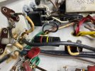
The two BLACK wires that come out of the chassis below the large transformer go to the Fuse Holder and one of the electrical plug-ins on the back panel. There is also 2 greens that go to a small tube and 2 reds and 2 yellows that go to the large main tube. Please see all the attached photos. The two blacks are reading 121 vAC.

There is also a Brown and White and they go to the Bridge Rectifier mounted on the side of the chassis. See pic.

Make sure the fuse is good, it’s only a one amp fuse. Don’t just look at it, check it with an ohm meter.
Fuse is 100% good.
Got line voltage at the transformer winding?
Yes? Then switch is good, fuse is good.
Let’s then proceed from there.
Please keep in mind I have no electronics repair training and have only worked on a few pieces of Tube stereo. You need to talk to me like a 12 year old. The more detail the better. I don't know what a terminal strip is.
 

Attachments

  • 1cd1d148-b08a-4559-84d3-e9e1e8576819.jpg
    1cd1d148-b08a-4559-84d3-e9e1e8576819.jpg
    184.6 KB · Views: 13
  • d58ca58b-bdac-43e0-9bb3-28f31ed9ab3f.jpg
    d58ca58b-bdac-43e0-9bb3-28f31ed9ab3f.jpg
    204 KB · Views: 9
  • feaf7f3b-452b-44e9-96e7-9d84e37236a6.jpg
    feaf7f3b-452b-44e9-96e7-9d84e37236a6.jpg
    186.9 KB · Views: 8
  • 2c17214b-c425-41bf-9aa6-90120dc181ba.jpg
    2c17214b-c425-41bf-9aa6-90120dc181ba.jpg
    213.5 KB · Views: 9
Last edited:
OK, I tried this both way with the switch on and off. One lead of my Ohm Meter connected to the Jumper wire that goes South off the Black wire from the outlets, and one lead on the Yellow wire, I got an OL reading. I tried the other Black and Yellow and White from Outlets and Yellow and got OL each time, no ohm read

sounds like the switch failed to me. It should not read open circuit with it turned on.
 
121VAC at the transformer indicates the switch is closed(good) and the fuse is good.
When you replaced the cap can did you solder the mounting tabs to the chassis?
They are the negative side of the caps. This is important.
A terminal strip is the part that wires and components are soldered to.
The rectifier in your #2 photo is an example. There are many.
I’d put the tubes back in and turn it on. Do the tube filaments lite up?
Or did the fuse blow? If the fuse held the filament winding of the transformer should lite them up.
Don’t use the dim bulb tester.
Recheck all your work. Once again…. Watch your fingers!
 
sounds like the switch failed to me. It should not read open circuit with it turned on.
I can remove it and rebuild it. Mechanics is my area of expertise.
When you replaced the cap can did you solder the mounting tabs to the chassis?
I did not solder the tabs to the chassis but the are very tight and making ground and one tab is soldered to an exposed hard wire and one tab is directly wired to the negative off the Bridge Rectifier.
I’d put the tubes back in and turn it on. Do the tube filaments lite up?
I never took any tubes out at any point. None of the tubes light up or come one because the stereo is not getting any power past the switch, I would guess.
Or did the fuse blow? If the fuse held the filament winding of the transformer should lite them up.
Don’t use the dim bulb tester.
Fuse is still good, and nothing lights up at all. No bulbs get warm or anything.


Can anyone tell me why I got readings in the PicoFarad range when I tried to measure capacitance of the 4 section Can Cap. As I stated earlier I know when you try to do with the the cap in circuit you get the wrong readings but in the PicoFarad range?
 
298588372229
Put this number in the EBay search box.
Get this Sam’s photofact and you might get this sorted.
Good luck!
BTW
Stop fussing over cap readings. H/H knows how to build cap cans correctly.
 
Here is the 69 Can Cap installed. The black stick points to the ground strap.
 

Attachments

  • 249c50d5-c03b-4d30-b928-a5987fa3ef75.jpg
    249c50d5-c03b-4d30-b928-a5987fa3ef75.jpg
    137 KB · Views: 9
  • 4d3dd4f9-598f-41d0-b331-bd057d76ef39.jpg
    4d3dd4f9-598f-41d0-b331-bd057d76ef39.jpg
    130.4 KB · Views: 7
It identifies all the components by value and location, and the color of the wires.
Also all the voltage test points.
Electronic and mechanical alignment and most important a clear, legible schematic.
Nothing like having that right in front of you and not having to deal with a computer, tablet or a phone.
 
Are you saying you grounded the black line (yellow arrow)?
NO, I pointed out several times that this black wire goes to the small Transformer that is mounted on the Wall of the chassis like the Bridge recitifier is mounted on the wall next to it.
The power supply schematic seems to show that connection as a (+) power source. A, B, C, or D connection. Right? This may be why you aren't getting any power to the unit.
I asked you to be more clear with your questions as I have no formal training, so I can not answer this question. You need to phrase you question like this, The Yellow on the Blah Blah goes to the Blah Blah.
Note: I have one suggestion. It seems you aren't using a dim-light current-limiting tool. Be SURE the unit has the correct fuse before powering it up. I see it as a 1-amp fuse — on the schematic. I usually buy a box of 5 for spares. :)
If you read the previous posts I made reference to my DBT several times. I thought DBT was the abbreviation for Dim Bulb Tester?

Mr Boochie, you have no idea how much I really really appreciate this help but I am not a professional and I have no formal training in electronics repair and very minimal work with Tube equipment. I keep struggling to understand what you are asking unless you keep the questions simple.

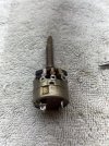
I think the problem was in the power switch. The front half of the switch is the volume and the back half with the click is the power switch part. When I tested the solder points for continuity between all 4 points there was none. Now I am getting a beep from my MM.
 

Attachments

  • 275daac8-f331-4bcc-9a4d-600aca859e7d.jpg
    275daac8-f331-4bcc-9a4d-600aca859e7d.jpg
    283.5 KB · Views: 3
  • 882bb843-30be-4d47-86bf-313afe058c93.jpg
    882bb843-30be-4d47-86bf-313afe058c93.jpg
    203.8 KB · Views: 3
  • 932d2733-1c16-4350-b5f2-176e3c8bd2f5.jpg
    932d2733-1c16-4350-b5f2-176e3c8bd2f5.jpg
    261.6 KB · Views: 3
Do yourself a favor and put the switch back together. There are no user serviceable parts. Mount it to volume pot and install the wires to the pot.
Then take the two black wires from the switch and splice them with the yellow wire from the switch. Put a wire nut on them.
Now your switch is bypassed and no longer in the circuit and the unit is live when you plug it in.
Careful now!
 
NO, I pointed out several times that this black wire goes to the small Transformer that is mounted on the Wall of the chassis like the Bridge recitifier is mounted on the wall next to it.

I asked you to be more clear with your questions as I have no formal training, so I can not answer this question. You need to phrase you question like this, The Yellow on the Blah Blah goes to the Blah Blah.

If you read the previous posts I made reference to my DBT several times. I thought DBT was the abbreviation for Dim Bulb Tester?
Okay, sorry. I will not ask anymore.

My posts are deleted.

Good luck with your unit!

9c04e894-bdc8-47e5-88a8-94bd753b7812.gif
 
Last edited:
Do yourself a favor and put the switch back together. There are no user serviceable parts. Mount it to volume pot and install the wires to the pot.
Then take the two black wires from the switch and splice them with the yellow wire from the switch. Put a wire nut on them.
Now your switch is bypassed and no longer in the circuit and the unit is live when you plug it in.
Careful now!
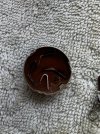
Too late, Its almost done. There was a lot of black crap inside the switch and I cleaned and polished all the contacts, but if it fails I may do what you are suggesting but I will need advise on how to wire it. Kind if weird how the stupid switch goes bad at the same time as the other work being done. I never should of laid my sandwich on the switch.
 
the contacts in those burn, its somewhat under-rated for the job. If the metal isn't melted away though you may get away with just cleaning it.

Probably died because of whatever was causing the fuse to blow. Just too much for a marginal part.
 
Back
Top Bottom