• The move to the new server is done. There are some software and database maintenance updates in process. This has us passing the hat around to help out. We appreciate any donations. Seriously, even a dollar helps. The payment page may be found here - https://www.audiokarma.org/support.html

The Fisher Phase Inverter Noose Revisited Part II (for 400 and 500/800B receivers)

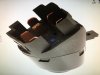
In the very beginning of this hobby for me I ran into several vintage units, where previous owners installed inline power switch because original in the front panel was either fused or failed otherwise. Installing relay was the reason to protect AC switch contacts. Some older VW starter solenoids were fed directly from the ignition switch causing premature ignition switch failure and often meltdown. In early 2000s, whenever I was replacing ignition switch, I started installing relay to power the solenoid. What do you know! Shortly after there was a recall or TSB describing this condition. Since then, every starter or ignition switch sold for affected model comes with the instruction sheet, referencing to "ACC" relay kit.

Back to Fisher world.
Please note that I have not made latest PI modification changes yet. For the moment, goal is to get voltages correct before any other changes are made.

Wall 122.6vac

With both CL-80 bypassed and outputs tubes biased at 21mA, B+ distribution as follows:
437v, 386v, 355v, 312v, 218v
AC heaters are at 6.59v
Screens are at 315v

With single CL-80 in the circuit and output tubes biased at 21mA, AC heaters are 6.46v, main B+ is 423v and screens are 304v

I think first scenario without thermistors shows desirable voltages but offer no protection in the event that wall voltage climbs. 6.59vac is pretty close to +5% limit (6.615vac)
Are there other thermistors that I could try that would be a better compromise?
EDIT: 2 x CL-80 in parallel? Or I'm overthinking it?

It's worth noting that my power supply is not modified as was suggested by @sony6060 but all can capacitors are new from Hayseed. There is no choke either. The only difference from stock form is R41 @ 2.2k.

Thanks for your help!
 
Last edited:
In your scenario, I would install one CL-80, which would seem to be ideal -- heater voltage is not low and <3% high, which is perfect. Your main B+ level is nearly identical to mine as well. The remainder of the voltages down stream will then be a product of your particular tubes and components installed, with any nominal deviation being insignificant.

Using the ignition switch to directly power the starter solenoid coil is a recipe for disaster!! What the heck were those VW engineers thinking? (besides cost control!) :)

Dave

Many domestic vehicles had ignition switch driving solenoid directly (through neutral safety or clutch switch) but those were much, much more beefier then modern ignition switch contact group. Below are 2 pictures for comparison.

Would it make sense to back bias down a bit since plate & screen voltages will be lower? That will bring B+ up a little too.

Thanks
 

Attachments

  • 93D00446-4A0A-449D-BC98-637EF0C2454A.jpeg
    93D00446-4A0A-449D-BC98-637EF0C2454A.jpeg
    54.6 KB · Views: 45
  • 42BEA09A-9A2D-42EA-8063-2D004889F575.jpeg
    42BEA09A-9A2D-42EA-8063-2D004889F575.jpeg
    47 KB · Views: 44
Dave,

Couple of questions before I add PI mod parts:

1. I don't have 62k resistor. I have placed parts order before you posted edit. I believe I have 59k and for sure 56k. Go with as close as I can get to 62k?
2. Both AF and PI stage plates will be powered from #3 B+ tap, which in my case will be somewhere around 345v, correct?
3. Could you please clarify AC balance adjustment procedure for my modified PI stage? The goal is to adjust trimmer to match exact resistance of the plate load 47k resistor, correct?
For the trimmer part, do I measure whole cathode string resistance to ground? Or just trimmer to ground?
4. What would be target for bias setting since plate / screen voltages will be lower?

Thank you for your help!
 
1. Yep. 56K works fine -- I just found 62K to be most centered over a wide variety of a significant number of tubes.

2. Yep again.

3. Yep. If you are following the version where you use the original 500K AC Balance controls, you adjust the resistance across the trimmer pot itself to equal the value of the 47K plate load resistor.

4. The target bias setting would remain unchanged.

Dave
 
#3.
No. I’m using 5k AC balance pot, as was specified in your revised PA schematic. I’m adding 62k (found 2 new 1/2 watt carbon films in the drawer!) shunted with 47uf.
 
Cathode to heater bias junction is where I measure to adjust the trimmer, right?
Confusing, having so many versions out there. Wouldn't that be more accurate to set AC balance with the scope?
 
In the modified power amplifier design, the 56K/180k parallel fixed resistance and 5K trimmer values in the cathode circuit of the inverter were chosen to help those with minimal test equipment, so they could get the most out of the modified design, while also accounting for particular qualities of the T1020-116 AX output transformers. With these transformers, it was found that the CT is not precisely placed at the center tap, so that the lowest distortion AC Balance point is not achieved when an equal push-pull signal is applied to it, but a slightly unequal one, that favors the blue/yel primary lead. The inverter's cathode resistance in the modified design takes this into account, as with the 5K trimmer control centered, the cathode leg then produces an optimum 45.2K, versus, versus the 47K in the plate leg. Your goal then is to have this section of the cathode resistance still represent 45.2K, working in connection with 47K in the plate section. The trimmer has enough range so that these plate and cathode sections can be made equal if you like, but from a pure design standpoint, minimum distortion will be produced with the values discussed.

Because the work you are doing to implement the new inverter biasing scheme into the modified power amplifier design has no effect on the AC Balance setting of the inverter, if you originally set the trimmer to produce a cathode resistance of 45.2K, and have not disturbed it since, then that setting will not change when adding the new 62K/47uF network with the modified design. Understand then that in your particular case, you still want the 56K/180K/5K trimmer components to produce a value of 45.2K, when 47.0K is installed in the plate circuit. The best way to find the optimum setting for the AC Balance control is to use a THD test set, and adjust the control for minimum distortion at a power level just below the onset of clipping. Without such equipment however, by centering the the AC Balance control of the modified design (or adjusting it for a value of 45.2K), it will closely approximate the lowest distortion setting.

Dave
 
I do not have distortion analyzer, so I will follow your adjustment method. One thing is strange though... I thought the goal is to set cathode resistance equal to plate load resistance. At least, that was the only recommended approach I have found posted. I guess I've missed one where you recommend setting cathode string to 45.2k vs. 47k.
My plate resistance reads 46.9k in one channel and 47.1k in another.

One thing I haven't found an explanation for is how added 62k resistor is not taken into an account for balance measurement. Tube plate draws current through the ground, which includes added 62k.
Just trying to understand...
 
Grind -- You've got to remember that we're dealing with two different types of voltages -- both AC (signal), and DC (static). The 62K resistor is adjusting the static operating current through the inverter tube so that it can bias itself correctly when operating from it's original B+ supply point, and in spite of a fairly wide range of grid voltages, as received from the plate of the previous stage. But in adding that resistor, the AC signal at the cathode did not change because of the large (47 uF) decoupling cap attached to the top of the 62K resistor -- which is also the bottom of the original cathode network. That cap bypasses any audio signal at that point straight to ground, but leaves the DC present unchanged. Therefore, no audio is being developed across the 62K resistor -- just DC voltage -- with the AC signal still developed across just the 56K/189K/5K trimmer elements. This is why the setting of the AC Balance adjustment is unaffected by the addition of the 62K resistor. Now if that 47 uF bypass cap weren't there and the 62K resistor were added, that really would create an imbalanced mess!

Dave
 
Got it! I thought that cap is a part of the answer but was not sure.
Are new AF & PI pin voltages posted somewhere? All mods were completed yesterday except for PI adjustment. Will fire it up tonight. Would be nice to know what voltages are in the ball park and what is considered to be off.

Thank you for your help!
 
Adjusted AC balance to 45.2k
Here are my voltages:

B+
425v
379v
351v (AF and PI)
311v
218v

EFB Screen is 307v

AC filaments are 6.52v biased with 62vdc.
It was interesting to find R36 / R37 at output tubes and not somewhere closer to power supply section. I was expecting to find 3 point terminal strip with both resistors junction grounded. Instead, they were individually grounded at V15 & V17 sockets.

V12/V13 voltages
PI plates 300v
PI cathodes 110v
AF plates 107v
AF cathode was close to "0" but I didn't have schematic at hand and had tester on high voltage range. Definitely below 1v so it's good

Dave-- please let me know if anything raises a flag.
Have a great weekend everyone!
 
Your voltages all look great. You'll likely find that the plate voltage of the AF Amplifier stage is 108 volts, since your meter was loading down the circuit. With low current stages employing a high value plate load resistor, it's usually best to measure the voltage drop across the plate load resistor, and subtract that from the B+ source voltage supply. That way, the meter produces less error when measuring circuit voltages. Your AF stage cathode voltage calculates to 0.86 vdc, which is perfect.

Dave
 
Thanks Dave!
I will take a reading across the plate resistor next time receiver is on the bench.

Currently listening through Klipsch KLF-20 pair that I repaired, rebuilt and upgraded several months ago.
So far, the best amplifier match for them is Sansui 9090 but I have to say that Fisher reproduces some sounds through them that I haven't heard before. Mid-range to low bass is absolutely amazing. Still, I haven't heard nothing better then Fisher and Cornwalls but Cornwalls seem to sound amazing with just about any amplifier, as long as it is in proper functioning condition.

As always, I have couple of questions and I will post new thread to keep this one dedicated to PI mod questions.

Thanks again!
 
Grind -- No doubt confusion can arise due to the different voltages presented on the modified schematic, versus those shown on the Fisher schematic. However, with different tube elements being supplied from different voltage sources in the modified design, it was really unavoidable at the time. With regards to your project, I would offer the following comments:

1. Since you have already previously installed the modified power amplifier section, you really only need to add the 62K resistor and 47 uF bypass cap to the phase inverter stage, which would then be added between ground, and the (originally) grounded terminal of the 5K AC Bal control used in the modified design. Similarly, heater bias would be taken from the new junction of these components as well. The advantage of this approach is that it allows you to use your existing AC Balance components. The 500K control with 56K shunt resistor shown on the revised noose removal design simply allows those who are starting with a stock receiver to retain the original AC Balance control to minimize cost. Either way works just fine.

2. In the modified design, you changed the B+ source for the AF Amplifier stage to the next lower B+ source (that supplying the tone control stages) -- but with the new noose removal procedure, that is no longer done (simplifying those starting with a stock unit). That is, the AF amplifier stage needs to remain connected to its original B+ source point as originally designed (Fisher labeled 320 Volts, supplying both the AF Amplifier and Phase Inverter stages). Therefore, you will need to reconnect this back as it was.

3. In your unit, R41 needs to remain at the modified value of 2.2KΩ (2 watt), since this value corrects for the screen grid current that no longer passes through this resistor when EFB™ is installed.

4. Understand that in your particular case, by converting to the new noose removal design, the significant improvement you are achieving is making available a heater bias voltage to eliminate the stress between the heater and cathode elements of the phase inverter tube -- which is surely a good thing. The primary goal of the new noose removal design however was to allow the driver tube to operate properly with a wide variety of tube characteristics -- rather than only with the rather narrow characteristics of Fisher's specified tubes. The heater bias voltage that the new design afforded was simply icing on the cake.

In the modified power amplifier design however, the issue of the driver tube operating properly with a wide variety of tube characteristics had already been addressed, so that with regards to that particular goal, the changes you are making will produce only little improvement. However, the new approach does allow for easily biasing the heater supply as stated, so it is still a very worthwhile project.

I hope this helps!

Dave

Dave in that order this suggestion you did can be added to the drawings plus the upgrading of the TL082 stage prior the AF 12AX7 preamplifier in the later 400 version that we did several years ago? My idea is do this mods in the drawings this weekend. Please let me know.

BTW sorry for be away for long time, with a new member in family and a new duties on the job makes the free time tight and scarce.

Regards to the AK family from Bogotá, Colombia.
 
Last edited:
Thanks Dimitri. Dave Emailed the same answer.

The complete answer........" the intent is that you lift the grounded ends of both R92 and R93 from ground, and then connect both of them to the new heater bias tap. "

Larry both points coming from each PI 500K new AC balance Resistor? I'm trying to assimilate all threads about it to made the drawing for the 400 later version but I´am still joining concepts.


Regards

Luis E.
 
Luis;
I did some circuit drawings for the P.I.'s for my Early 400 and posted them here in this thread.
https://audiokarma.org/forums/index.php?threads/400-phase-inverter-mod-install-project.866989/

Take both of the heaters and extend them to the same point (BOTH SIDES got the BONUS UPGRADE but only one side connected for the HTR BIAS) The 500KΩ pot (R84) writing in between the Pin 3 and pin8 I missed when I redrew the mods in.(It's been removed) The 500/800B/400 mods move it to the UPPER side and revalue it as 25KΩ pot.

I did the "BONUS" upgrade on the BOTH sides (See Dave's original drawing for the 800/500B/400 in the 1st post on the thread). Drawings below show 1st the BASIC P.I. upgrade, and 2nd the BONUS Upgrade .
(NOTE: HTR Strings from R92-93 (R36-37) connect to one P.I. HTR BIAS TAP or the other. Connect the free ends of the R's together and run a lead to the closest P.I. HTR Bias tap.
Here's What I came up with based on Dave's Drawings
BASIC UPGRADE 400 BASIC UPGRADE TO P-I.jpg

BONUS UPGRADE. NOTE that the P.I. Adjustment pot is Moved to the top and DeValued to 25K.
(I edited out the reference to R84 500KΩ)
400 improved phase inverter Bonus upgrade.jpg

LEFT SIDE IS IDENTICAL for EACH Version. It applies to ALL versions of the 400.

Larry
 
Last edited:
10. To set the AC balance control on the 500/800B receivers: Measure the value of the 47K resistor in the cathode leg of the phase inverter section and note the value. Measure the value of the AC Balance control/33K resistor combination in the plate leg, and set the control so that the total of the control and 33K resistor equals that of the 47K resistor measured previously.
Dave,
How is the inverter AC balance adjusted when this option is used as an upgrade for the late model 400 receiver?
I remember those OTs have off-center primaries and your procedure describes adjusting this type of inverter design in 500/800B receivers but not in 400.
Thanks
 
Back
Top Bottom