• The move to the new server is done. There are some software and database maintenance updates in process. This has us passing the hat around to help out. We appreciate any donations. Seriously, even a dollar helps. The payment page may be found here - https://www.audiokarma.org/support.html

The Fisher X-1000 and EFB

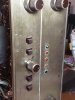
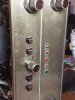
For anyone interested, here is a pic of a unit I just finished up for a client. For his particular needs, besides performing a complete and full restoration, the following modifications have also been installed:

1. Individual cathode resistors have been installed.
2. Screen Stability resistors have been installed.
3. AC power to the unit is now switched by relay contacts, with the power switch now only activating the relay coil.
4. The Aux 1/Tape Monitor bleed circuits have been removed.
5. The permanent low frequency filters have been removed.
6. The Reverb IN/OUT jacks have now been converted to proper Pre OUT/Pwr IN jacks.
7. The Headphone Channel Identity issue has been corrected.
8. All Remote Control socket and Space Expander phone jack wiring has all been removed.
9. The Loudness Control has been converted to values used in the 400CX-2 preamplifier circuit.
10. The output tubes (when installed) now operate under the complete control of EFB™ Control and Screen Grid regulators.
11. The power supply has been modified to allow for indefinite operation with the output tubes removed from the amplifier. Along with the work done in #6 and #9 above, this allows the unit to effectively operate and produce all the sonic qualities of a 400CX-2 preamplifier at the new Pre/OUT jacks, providing all of the most important features of that model as well.

Dave
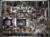
SAM_3271.JPG
 
Dave - I'm interested in your #5 - low frequency filters removed. Does that mean there are no restrictions on how low in frequency the audio signal can flow through the circuit all the way to the output transformers? I'd be very interested in that circuit (or I guess it would be the removal of said circuit) if you can draw a diagram. That would be for my 500-C. Thanks, Thorne
 
I would like to do both those mods. Do you have a link that explains exactly what to do.
No link...I may be able to post some pics, though. I should have took some pics of the stock set up, before I did it. Certainly like to have some stock (under the hood pics of Fisher X-1000, also.
If I knew how well it would turnout, I would of documented much better.
My Tech said it is the quietest amp, he ever heard.
This all started as a project to put Cardas. RCAs in place..vintage RCAs do not work with HFC. ICs. Anyway I started..got jammed up..so my tech took over. Well, I set up my back up home system and let him do the things to the Fisher, that I seen as The Time to do it. First it was just the expander, then the low level switch. That is when he said it is the quietest amp he ever heard. Than I told him to remove all but the phase reverse switch.
Than he said it was even quieter. Now I knew he was getting into it..he suggested four resistors to bias the outputs. I heard of that, so said go ahead !
Now he suggested take out phono section, as I use custom PSU. and phono preamp. I am feeling that urge, now.
I started out rebuilding back to stock, at Pavick. Museum. Had no idea the potential of this intregated amp.
The X1000 has a huge power transformer, besides output transformers. Robust power supply, too.
This has really turned into a bucket list item..that I am somewhat obsessed with, at the moment. Perhaps I should go back to drinking..NOT!
 
Dave - I'm interested in your #5 - low frequency filters removed. Does that mean there are no restrictions on how low in frequency the audio signal can flow through the circuit all the way to the output transformers? I'd be very interested in that circuit (or I guess it would be the removal of said circuit) if you can draw a diagram. That would be for my 500-C. Thanks, Thorne
As I managed to motorboat mine with adding too much gain with my Loki in circuit, I would have to be careful with the throttle lol
 
For anyone interested, here is a pic of a unit I just finished up for a client. For his particular needs, besides performing a complete and full restoration, the following modifications have also been installed:

1. Individual cathode resistors have been installed.
2. Screen Stability resistors have been installed.
3. AC power to the unit is now switched by relay contacts, with the power switch now only activating the relay coil.
4. The Aux 1/Tape Monitor bleed circuits have been removed.
5. The permanent low frequency filters have been removed.
6. The Reverb IN/OUT jacks have now been converted to proper Pre OUT/Pwr IN jacks.
7. The Headphone Channel Identity issue has been corrected.
8. All Remote Control socket and Space Expander phone jack wiring has all been removed.
9. The Loudness Control has been converted to values used in the 400CX-2 preamplifier circuit.
10. The output tubes (when installed) now operate under the complete control of EFB™ Control and Screen Grid regulators.
11. The power supply has been modified to allow for indefinite operation with the output tubes removed from the amplifier. Along with the work done in #6 and #9 above, this allows the unit to effectively operate and produce all the sonic qualities of a 400CX-2 preamplifier at the new Pre/OUT jacks, providing all of the most important features of that model as well.

Dave

View attachment 2163602
I think Pink Floyd has a song out about your X-1000, Dave.
"Welcome to the Machine"
 
Thorn -- Fisher built in permanent 12 db/octave LF filters in virtually all of their (at least) stereo units, as a fire wall against the rumble noise produced from the use of record changers, and to help prevent LF acoustic feedback when the speakers and record changer were mounted together in a console. The effects of the LF tailoring produced by these filters always begins above 20 Hz, with how high the tailoring begins above that frequency depending on the model, and its ability to handle LF information. For those restoring a Fisher console to it's former glory, I would surely recommend leaving these filters in place, as the original operating concerns then (obviously) still exist. But for those with Fisher equipment whose installation is not in a console setting, removal of these filters can provide enhanced enjoyment of today's digital audio sources, particularly when the program material includes LF information that is much lower in frequency than that which could be captured back in the late 50s/early 60s on vinyl. And, a more open installation usually doesn't include a record changer anymore. When the filters are removed, while the intended LF tailoring is also removed, response is hardly then flat down to DC as there are other practical matters that still prevent this from occurring (coupling caps, OPTs, even the duty cycle of the output tubes, etc.). However, with the filters removed, the low end frequency response is then very flat down to below 20 Hz (typically to about 10-12 Hz depending on the unit), so that for all practical purposes, there are then no limitations placed on the reproduction of the vast majority of recorded LF audio signals.

Removal of the filters is extremely easy, and involves shorting out a very small coupling cap used at the grid of an early small signal stage (I always opt to completely remove the cap and then install a jumper). In the 500C, this would be C35 and C36, HOWEVER.........

In specifically the 500C and 800C receivers, I do NOT recommend removing these filters unless you have no issue with a very definite side effect produced by the FM Automatic circuits when the filters are removed. In these receivers, included is a diode matrix switching circuit -- controlled by the FM Automatic circuits -- that toggles between the FM MPX Stereo signals from the MPX-65 MPX decoder, and the conventional Mono signal taken directly from the output of the Ratio Detector IF transformer. This diode matrix switching circuit is an excellent answer that Fisher came up with to eliminate the problems associated with switching audio signals by relay contacts (as used in some of their earlier FM MPX tuners that had this feature). But, the diode matrix switching circuit has one caveat -- it produces a rather significant DC pulse every time it changes state. As a result, if the permanent LF filters are removed, this DC pulse -- if left un-attenuated -- (as happens if the permanent filter is removed), then temporarily overloads the very stage where the permanent LF filter was removed from. The result is that when tuning across the FM band, as the FM Automatic circuits trigger between FM Stereo MPX and FM Mono reception, the switching event is no longer precise and immediate but rather, displays a notably slow, even lazy characteristic, as the input audio stage works to recover from the overload created from each pulse.

If this doesn't bother you, or you don't use the FM section -- or you leave the selector switch permanently in either the FM Mono or FM Stereo positions (where no automatic switching occurs), then removal of the filters is of no concern. But if you do use the FM Automatic position, just be aware of the collateral issue created with this function if the filters are removed.

I hope this helps!

Dave
 
The OPT transformers on the X-1000 are some of the finest that Fisher ever produced, capable of a low distortion LF power response down to just below 20 Hz at 50 watts RMS. Quite remarkable for an integrated amplifier from the early 60s.

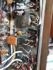
For those wanting a look at the underside of a stock late version X-1000, this is a pic of the unit I discussed in post #21 before work began:
SAM_3236.JPG

Dave
 
Dave - As always your attention to detail and willingness to be incredibly helpful and educational to us all is so very much appreciated, especially by me who is on the learning path still. Your post was very helpful, thank you so very much. I'll give your post much thought before I go fiddling about which I so enjoy doing in my 500-C. Thorne
 
Dave,
I messed up. I made a picture of where I was recapping for reference, however I did not move caps and resistors out of line of site to tube pin outs. I already recapped channel A with Jupiter beeswax. I did not have the two needed .10 caps for channel B until today.I
I am posting V10 and V9 pinouts.View attachment 2164195 Where do I connect I connect .10 cap lead to pin out V10 position represented hy image top left.? Than the V9 is the represented image, next right, to V10 position image.
Which pin out do I attach 2nd .10 cap lead to, on V9 pin outs? I THANK YOU in advance. I will post pics of completed bypasses of my unit later, when I open it back up, to attempt to finish the job. 20210309_231337.jpg pick of work done, so far
 
Dave,
I messed up. I made a picture of where I was recapping for reference, however I did not move caps and resistors out of line of site to tube pin outs. I already recapped channel A with Jupiter beeswax. I did not have the two needed .10 caps for channel B until today.I
I am posting V10 and V9 pinouts.View attachment 2164195 Where do I connect I connect .10 cap lead to pin out V10 position represented hy image top left.? Than the V9 is the represented image, next right, to V10 position image.
Which pin out do I attach 2nd .10 cap lead to, on V9 pin outs? I THANK YOU in advance. I will post pics of completed bypasses of my unit later, when I open it back up, to attempt to finish the job. View attachment 2164214 pick of work done, so far
Screenshot_20210315-172504_Google.jpg
 
Dave, Why couldn't a low filter be added to just the multiplex output signal path? FM typically has a lower limit of 50Hz.
 
I would like to do both those mods. Do you have a link that explains exactly what to do.
Ok have some pics of bypasses and Cardas rcas
 

Attachments

  • 20210315_222515.jpg
    20210315_222515.jpg
    97.9 KB · Views: 27
  • 20210315_221231.jpg
    20210315_221231.jpg
    156.2 KB · Views: 30
  • 20210315_221227.jpg
    20210315_221227.jpg
    156.3 KB · Views: 30
  • 20210315_222320.jpg
    20210315_222320.jpg
    65.7 KB · Views: 31
  • 20210315_222515.jpg
    20210315_222515.jpg
    97.9 KB · Views: 24
  • 20210315_222515.jpg
    20210315_222515.jpg
    97.9 KB · Views: 23
Last edited:
Fred -- It certainly could -- although at 12 db/octave something active would need to be included. In the tuners that include FM Automatic, they include a level control between the output of the diode matrix switching circuit, and the input of the AF amplifier stage. Since the tuners output such a high level, the tuner level controls are normally backed down pretty good, which prevents any overloading. Typically, the output from the tuner section of the receivers is pretty hot as well, so maybe just adding some attenuation at the output of the matrix circuit might prevent the overload as well.

Hot -- The 0.1 uF coupling cap between V10 and V9 connects to pin 6 at V10, and pin 2 of V9, which represents Channel B.

Dave
 
Thank you so much Dave. I managed to paint myself into a corner..should have just waited until I had all caps at hand. I sure like you have done with that amp !
I will be like Charly Heston. ..they can have my X-1000, when they pry my cold dead fingers from the volume control.
 
Fred -- It certainly could -- although at 12 db/octave something active would need to be included. In the tuners that include FM Automatic, they include a level control between the output of the diode matrix switching circuit, and the input of the AF amplifier stage. Since the tuners output such a high level, the tuner level controls are normally backed down pretty good, which prevents any overloading. Typically, the output from the tuner section of the receivers is pretty hot as well, so maybe just adding some attenuation at the output of the matrix circuit might prevent the overload as well.

Hot -- The 0.1 uF coupling cap between V10 and V9 connects to pin 6 at V10, and pin 2 of V9, which represents Channel B.

Dave
So I thought I would ask an authority on the Fisher X1000 integrated amp. Given that the Fisher X1000 has EL34 outputs with the plates running at 412 volts, and the Dynaco ST70 has EL34 outputs with the plates running at 410 volts, the Fisher X1000 puts out 50 watts RMS and the Dynaco puts out 35 watts RMS. Why the disparity with identical tubes and virtually identical plate voltages?
 
The ST-70 operates the output tubes in an Ultra-Linear circuit, whereas the X-1000 operates the tubes in a classic Pentode design. The X-1000 also uses a SS rectifier circuit that has a little stiffer power supply (less droop under full power conditions), where as the 70 uses a rectifier tube that is a limiting factor in the power supply design. Driven individually however, each channel of the ST-70 is capable of about 40 watts RMS power output. Note that is what the MK IV amplifier is rated at -- it is basically 1/2 of an ST-70.

I hope that helps!

Dave
 
The ST-70 operates the output tubes in an Ultra-Linear circuit, whereas the X-1000 operates the tubes in a classic Pentode design. The X-1000 also uses a SS rectifier circuit that has a little stiffer power supply (less droop under full power conditions), where as the 70 uses a rectifier tube that is a limiting factor in the power supply design. Driven individually however, each channel of the ST-70 is capable of about 40 watts RMS power output. Note that is what the MK IV amplifier is rated at -- it is basically 1/2 of an ST-70.

I hope that helps!

Dave
So apparently the Ultra-Linear was where the screen grid windings on the output transformer were a compromise or a mixture of class A and classic Pentode design. So the power output would be less given the screen grid windings were not for the most power output. I think Hafler popularized such but did not hold the original patent. The above is based upon a cursory google search, which happily still functions for search capability.
 
Back
Top Bottom