• The move to the new server is done. There are some software and database maintenance updates in process. This has us passing the hat around to help out. We appreciate any donations. Seriously, even a dollar helps. The payment page may be found here - https://www.audiokarma.org/support.html

The Fisher XP44 crossover cap reading

nonost

New Member
Hi. I'm going to replace the crossover caps of a couple old The Fisher XP44 I bought.

https://www.radiomuseum.org/r/fisher_two_way_speaker_system_xp_44.html

I'm used to read cap values but these make me doubt. It says:

4 MF 25 VNP

I guess the "25 VPN" is for 25 volts non-polarized.

You might think the '4 MF' is for 4uF but my tester reads 15uF. Are these caps so off that they no longer keep their capacitance? It looks a bit extreme, since the speakers sound right.

The caps are grey metal can electros. The logo is an 'M' with a dash across it. Made in Mexico

Cheers!
 
Register to hide this ad
I'm also doing the maths with online apps and I can't get the numbers.

The inductor is 1.62mH and the speakers 8ohm and 4ohm. Maybe radiomuseum is wrong about the 1000hz crossover.
 
I'm also doing the maths with online apps and I can't get the numbers.

The inductor is 1.62mH and the speakers 8ohm and 4ohm. Maybe radiomuseum is wrong about the 1000hz crossover.

The nominal impedance of speakers is an imaginary number. For most drivers, impedance varies over the driver's frequency range. Nominal impedance should not be used for crossover calculations. What counts is the actual impedance at the desired crossover frequency.

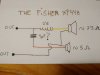
Since you apparently have the crossover in front of you, why not sketch out the crossover schematic and post it here. Knowing what the circuit looks like would make it easier to see what is going on.
 
The inductor says 2.6 on its own plastic. Sorry, I said 1.6 in a previous message.

I don't have any way to measure it though.
 

Thanks for the schematic.

Each of the drivers has a first order filter. I would trust the original designers and replace the cap with one having the same capacitance value. The voltage rating is a minimum and higher voltage ratings can be used without impacting the crossover.

I assume that the driver ohmic values are resistance values you measured, which means those are the dc resistance of the voice coils. The dc resistance values are only good for identifying if a particular driver is nominally 4 or 8 ohms. Impedance varies with frequency and generally a graph of impedance vs. frequency is used for crossover design.
 
Thanks for the schematic.

Each of the drivers has a first order filter. I would trust the original designers and replace the cap with one having the same capacitance value. The voltage rating is a minimum and higher voltage ratings can be used without impacting the crossover.

I assume that the driver ohmic values are resistance values you measured, which means those are the dc resistance of the voice coils. The dc resistance values are only good for identifying if a particular driver is nominally 4 or 8 ohms. Impedance varies with frequency and generally a graph of impedance vs. frequency is used for crossover design.

4uF looks ok? The cap says 4 MF but my tester reads 15uF. If so, would a 3.3uF or 4.7uF cap be fine? I can't get 4uF caps easily.

Thanks.
 
4uF looks ok? The cap says 4 MF but my tester reads 15uF. If so, would a 3.3uF or 4.7uF cap be fine? I can't get 4uF caps easily.

Thanks.

Ignore the tested value. Caps are tested to determine if they meet specifications, and those specifications are based on the printed label (plus others from published spec sheets). Electrolytic caps have a typical lifetime of about 10 to 20 years. Those caps are almost 50 years old. They are out of spec. I do not waste my time measuring caps that are that old because they are likely out of spec and, since they have to be removed to be test, might as well install good ones instead of an old one.

In your case, the cap is labeled "4 MF 25 VNP." Per the label, your cap has a 4 uF or mfd) capacitance value with a 25 volt rating for a non-polarized capacitor. I would recap using a 4uF poly cap, such as this one from Parts Express:
https://www.parts-express.com/dayton-audio-dmpc-40-40uf-250v-polypropylene-capacitor--027-421

Also, when I recap, I determine if the caps are original or not. If the original caps are installed, I replace with new caps of the same value. If I can find a schematic, I may compare the schematic to what is installed, but I still prefer to rely on the installed value because oftentimes manufacturer schematics are not updated or reflect what was used in all cases.
 
Ignore the tested value. Caps are tested to determine if they meet specifications, and those specifications are based on the printed label (plus others from published spec sheets). Electrolytic caps have a typical lifetime of about 10 to 20 years. Those caps are almost 50 years old. They are out of spec. I do not waste my time measuring caps that are that old because they are likely out of spec and, since they have to be removed to be test, might as well install good ones instead of an old one.

In your case, the cap is labeled "4 MF 25 VNP." Per the label, your cap has a 4 uF or mfd) capacitance value with a 25 volt rating for a non-polarized capacitor. I would recap using a 4uF poly cap, such as this one from Parts Express:
https://www.parts-express.com/dayton-audio-dmpc-40-40uf-250v-polypropylene-capacitor--027-421

Also, when I recap, I determine if the caps are original or not. If the original caps are installed, I replace with new caps of the same value. If I can find a schematic, I may compare the schematic to what is installed, but I still prefer to rely on the installed value because oftentimes manufacturer schematics are not updated or reflect what was used in all cases.


I'm in Europe and I can't find a 4uF. It's a strange value. I will can get some 3.3uF and 4.7uF and hope the tolerances will get me closer to the 4uF value.

Thanks for your help, I really appreciate it.
 
I'm in Europe and I can't find a 4uF. It's a strange value. I will can get some 3.3uF and 4.7uF and hope the tolerances will get me closer to the 4uF value.

Thanks for your help, I really appreciate it.

The 3.3 and 4.7 uF caps are both almost 20% away from the desired capacitance value. That large of a deviation will shift the crossover frequency and create either a null or a peak. It is best to use a capacitance value as close as possible.

I suggest finding two caps where the value adds up to 4 uF or very close, maybe 0.2 uF variation maximum (5%). If you wire the capacitors in parallel, the values add and it is the same as one cap.

You can use a 1uF and a 3uF, or two 2 uF, or 1.8 uF and 2.2 uF, etc.

If you can find 1 uF caps, use four of them in parallel.
 
Back
Top Bottom