Hello,
I have a question to those knowledgeable about this JVC receiver.
I have this beautifull tank of a receiver. I have recapped most of it and replaced all the infamous 458 transistors.
I turn it on and everything works. So far so good.
But. Everytime I turn it on there is a rather loud pop in my speakers on the exact moment the relay is activated, also with the volume down. This was both with the old and new relay I installed.
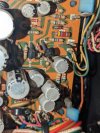
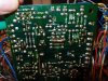
But I remembered the first time I opened the receiver and looked at the power supply/protectionboard I saw this weird ”constelation” of af diode, resistor and transistor tied together. See the picture. (two transistors in the middle). On the backside of the pcb there is also a resistor between the emitter and base.


This looked weird to me and I thought it probably wasnt factory.
But now I think it is, because I saw a picture of another JVC 5456 with the same ”constelation”.
So I changed it back to the way it was (thank God I took some pictures beforehand) before and expected that it would take care of this popping sound.
The good news is. The receiver powers up without a problem, the relay is activated- but still this popping sound.
So this is a longish story.I hope you still here;-)
My questions:
- Does anyone know about this problem or is it just my receiver?
- Most important. Does anyone have an updated version of the Powersupply/protectionboard part.
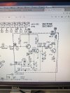
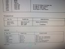
The service manual you can download from Hifi engine and the likes don't seem to correspond with what I have.
Thank you for your time!
I have a question to those knowledgeable about this JVC receiver.
I have this beautifull tank of a receiver. I have recapped most of it and replaced all the infamous 458 transistors.
I turn it on and everything works. So far so good.
But. Everytime I turn it on there is a rather loud pop in my speakers on the exact moment the relay is activated, also with the volume down. This was both with the old and new relay I installed.
But I remembered the first time I opened the receiver and looked at the power supply/protectionboard I saw this weird ”constelation” of af diode, resistor and transistor tied together. See the picture. (two transistors in the middle). On the backside of the pcb there is also a resistor between the emitter and base.
This looked weird to me and I thought it probably wasnt factory.
But now I think it is, because I saw a picture of another JVC 5456 with the same ”constelation”.
So I changed it back to the way it was (thank God I took some pictures beforehand) before and expected that it would take care of this popping sound.
The good news is. The receiver powers up without a problem, the relay is activated- but still this popping sound.
So this is a longish story.I hope you still here;-)
My questions:
- Does anyone know about this problem or is it just my receiver?
- Most important. Does anyone have an updated version of the Powersupply/protectionboard part.
The service manual you can download from Hifi engine and the likes don't seem to correspond with what I have.
Thank you for your time!